u
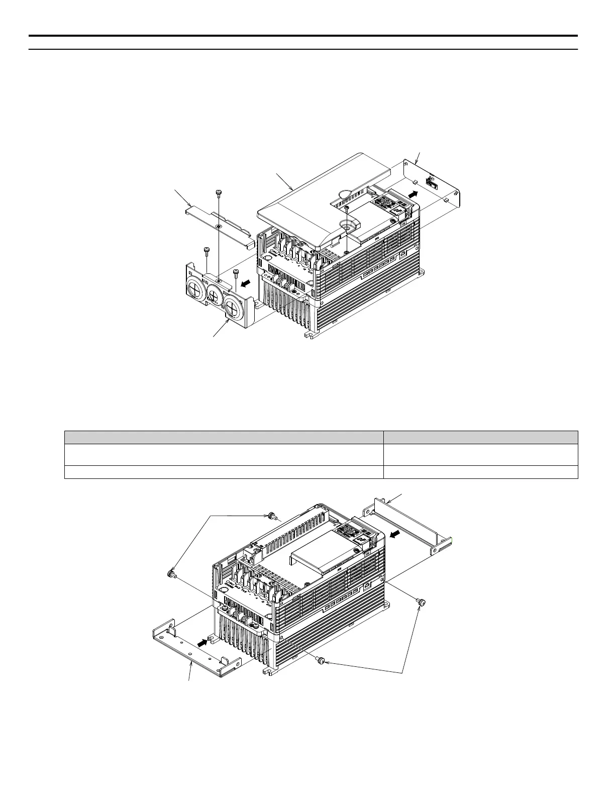
Procedure 5 (Enclosure: NEMA Type 1)
1.
Remove Drive Covers and Brackets
a.
Remove the Terminal Cover.
b.
Remove Top Cover.
c.
Remove NEMA Type 1 Cover.
d.
Remove Conduit Bracket.
NEMA1 Cover
Terminal Cover
Top Cover
Conduit Bracket
Figure 8 Drive Cover and Bracket Removal
2.
Install Attachments 1 and 2
a.
Install Attachment 1 and Attachment 2 to the mounting holes on the side of the heatsink using M5 x12
pan-head screws as shown in Figure 4.
Table 7 Installation Fasteners by Model for Figure 4
Drive Model Installation Fasteners
CIMR-Vo2o0030 to 0056
CIMR-Vo4o0018 to 0038
M5 x 12 Pan-head Screws (x4)
CIMR-Vo2o0069
M6 x 14 Pan-head Screws (x4)
Attachment 1
Attachment 2
M5 x 12 Pan-head Screws (x2)
(screw size varies by model)
M5 x 12 Pan-head Screws (x2)
(screw size varies by model)
Figure 9 Diagram shown for Model CIMR-Vo2o0030
3.
Install Attachment 3
5 Installation Procedure by Drive Model
18
YASKAWA V1000/J1000 AC Drive External Heatsink Kit Option Manual EZZ020568

 Loading...


