12 YASKAWA ELECTRIC TOBP C730600 60C V1000 Option SI-EN3/V Installation Manual
4 Option Components
4 Option Components
u
SI-EN3/V Option
Figure 1
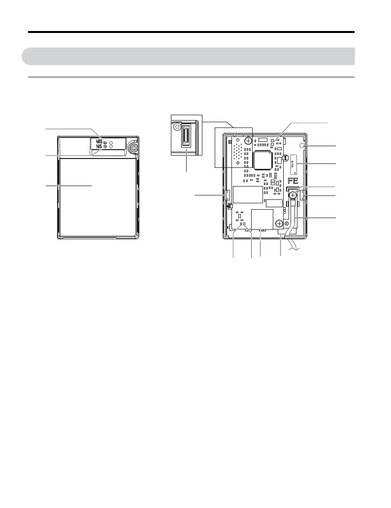
Figure 1 Option Unit Components
A – LED (MS)
<1> H – Mounting tabs
B–LED (NS)
<1> I – Ground wire <2>
C – Option cover J – Pass-through hole for wire
<1> Refer to Option LED Display on page 16 for details on the LEDs.
<2> A selection of ground wires are packaged loose in the option shipping package. Connect the appropriate ground
wire based on drive model during installation.
D – EtherNet/IP PCB K – Communication connector CN1 (RJ45)
E – Screw hole (attaching option cover) L – LED (LINK/ACT)
<1>
F – Nameplate M – LED (10/100) <1>
G – Functional earth cable connection (FE) N – Option connector
B
C
H
E
D
H
G
I
J
N
F
K
00000000000000
SI-EN3/V
1XXX
L
M
Option with cover removed
Underside
Option with cover attached

 Loading...


