APPENDIX 3 CONSTANTS LIST
63
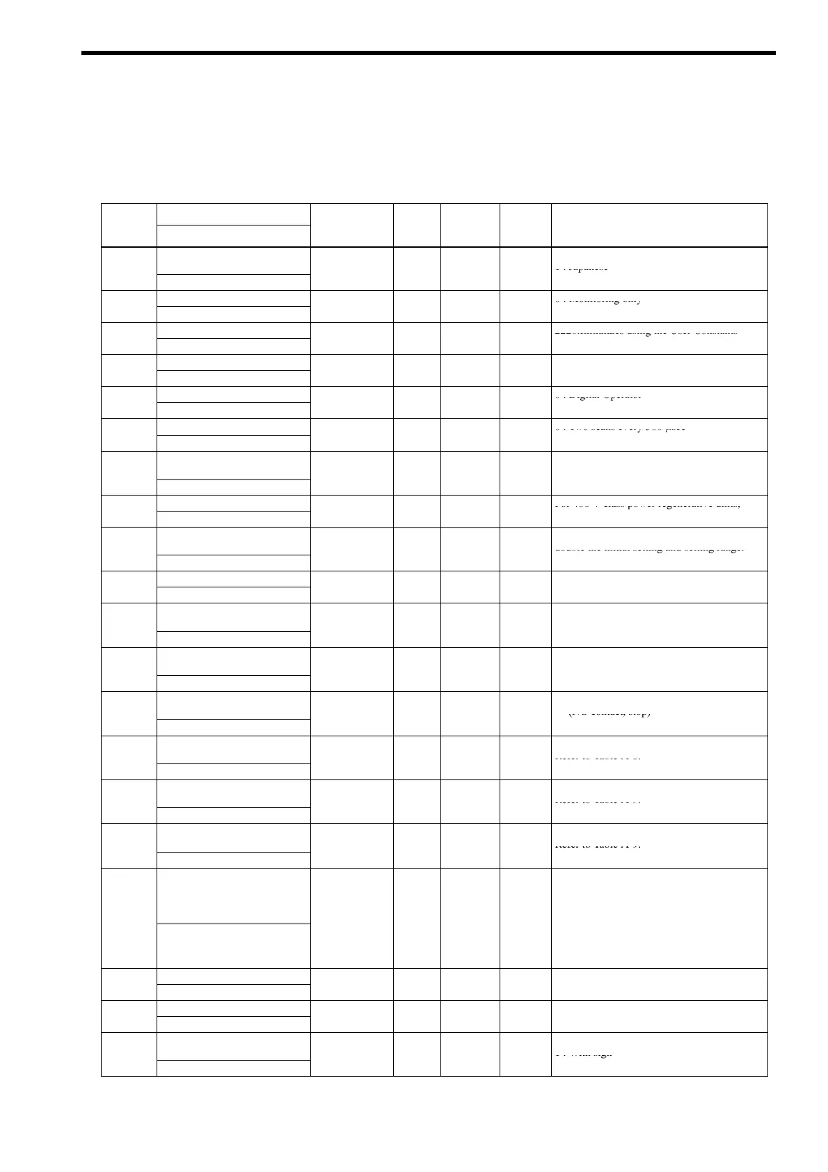
Table A-7 Constant List
Constant
Name
Factor
Change
Access
No.
Display
Setting Range
Setting
during
Operation
Level
Description
A1-00
Language selection for
operator display,
0
1 0
f
A
0 : English
1 : Japanese
-
[Select Language]
,
Constant access level
0 : Monitoring only
A1-01
[Access Level]
0 to 9999 4
f
A
4 : Advanced (A)
Initialize
2220:Initializes using the User Constants
A1-03
[Init Parameters]
0000 to 9999 0000
×
A
Password 1 (Input)
A1-04
[Enter Password]
0000 to 9999 0
×
A
Operation method selection
0 : Digital Operator
B1-02
[Run Source]
0, 1 1
×
A
1 : Control circuit terminals
Read sequence input twice
0 : Two scans every 500 µsec
B1-06
[Cntl Input Scans]
0, 1 1
×
A
1 : Two scans every 5 ms
C8-17
Automatic operation stop
current
10 to 100 % 50
×
A
-
[Autorun Iout]
Bias voltage at operation start
For 400 V class power regenerative units,
C8-18
[V Bias of Run]
0.0 to 50.0 V 2.0
×
A
double the initial setting and setting range.
C8-19
Hysteresis voltage width at
operation start/stop
0.5 to 50.0 V 3.0
×
A
For 400 V class power regenerative units,
double the initial setting and setting range.
-
[V Width of Stop]
.
.
.
Min. operating time
C8-20
[Minimum Run Time]
0.0 to 600.0 sec 1.0
×
A
F1-10
Excessive frequency
deviation detection level
1.0 to 10.0 Hz 3.0
×
A
-
[FDEV DetectLevel]
.
.
.
F1-11
Excessive frequency devi-
ation detection delay time
0.0 to 255.0 sec 70.0
×
A
-
[FDEV Detect Time]
.
.
.
H1-01
Multi-function input
(terminal S3)
0to2F 24 f A
24 : External fault
(NO contact, stop)
-
[Terminal S3 Sel]
Refer to Table A-8.
H1-02
Mlti-function input
(terminal S4)
0to2F 14
f
A
14 : Fault reset
Refer to Table A-8.
-
[Terminal S4 Sel]
H2-02
Multi-function input
(terminal M1-M2)
0to20 6 f A
6 : Regenerative unit ready
Refer to Table A-9.
-
[Terminal M1 Sel]
H2-03
Multi-function input
(terminal M3-M4)
0to20 0
f
A
0 : During Run
Refer to Table A-9.
-
[Terminal M3 Sel]
H4-01
Multi-function AO
(terminal AM-AC)
0to21 5 f A
0 : Not used
2 : DC bus voltage (U1-02)
4 : Power supply voltage (U1-04)
5 : Current at power side (U1-05)
-
[Terminal AM Sel]
7 : Power at power side (U1-07)
8 : Power supply frequency (U1-08)
21 : Voltage deviation input (U1-21)
Refer to Table A-10.
Gain (terminal AM-AC)
H4-02
[Terminal AM Gain]
0.00 to 2.50 0.50
f
A
Bias (terminal AM-AC)
−10.0 to
H4-03
[Terminal AM Bias]
−
.
+10.0 %
0.0
f
A
H4-07
Analog output signal polarity
selection
0
1 1 f A
0 : Without sign
1 : With sign
-
[AO Level Select]
,

 Loading...


