64
Constant
Name
Factor
Change
Access
No.
Display
Setting Range
Setting
during
Operation
Level
Description
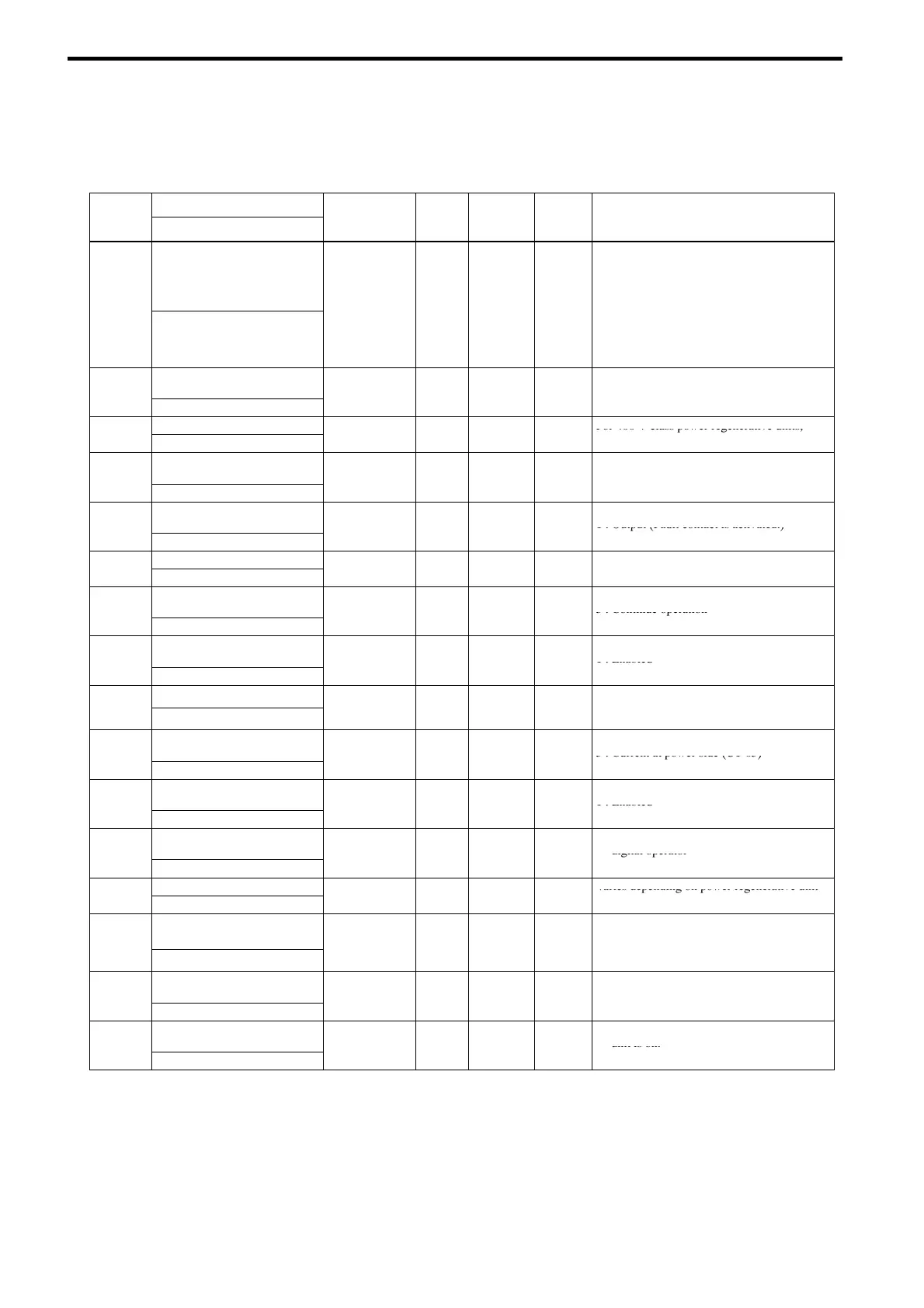
L2-01
Momentary power loss
detection
0to2 0
×
A
0 : Fault
1 : Operation continues within power loss
ridethrough time
2 : Operation continues if control power
su
l
is hold.
-
[PwrL Selection]
.
Note : Even if L2-01 is set to 1 or 2, the
power regenerative unit may detect a
fault if momentary power loss occurs
during regeneration.
L2-02
Momentary power loss
ridethru time
0.0 to 2.0 2.0
×
A
-
[PwrL Ridethru t]
.
.
.
Undervoltage detection level
For 400 V class power regenerative units,
L2-05
[PUV Det Level]
150 to 210 V 190
×
A
double the initial setting and setting range.
L5-01
Number of auto restart
attempts
0to10 0
×
A
-
[Num of Restarts]
L5-02
Auto restart operation
selection
0
1 0
×
A
0 : Not output (Fault contact is not activated.)
1 : Output (Fault contact is activated.)
-
[Restart Sel]
,
Overheat pre-alarm level
L8-02
[OH Pre-Alarm Lvl]
50 to 110 deg 95
×
A
L8-03
Operation selection after
overheat pre-alarm
1
3 3
×
A
1 : Stop
3 : Continue operation
-
[OH Pre-Alarm Sel]
,
L8-07
Power supply open-phase
protection selection
0
1 0
×
A
0 : Disabled
1 : Enabled
-
[Ph Loss In Sel]
,
Monitor selection
4 : Power supply voltage (U1-04)
o1-01
[User Monitor Sel]
4to8 8 f A
7 : Power at power side (U1-07)
8 : Power supply frequency (U1-08)
o1-02
Monitor selection after
power up
2to4 2 f A
2 : DC bus voltage (U1-02)
3 : Current at power side (U1-05)
-
[Power-On Monitor]
4 : The monitor item set for o1-01
o2-01
LOCAL/REMOTE key
enable/disable
0
1 1
×
A
0 : Disabled
1 : Enabled
-
[Local/Remote Key]
,
o2-02
STOP key during remote
operation
0
1 0
×
A
0 : Enabled during run command from the
digital operator
-
[Oper STOP Key]
,
1 : Enabled
kVA selection
Varies depending on power regenerative unit
o2-04
[Regen Unit Model]
00 to FF
:
×
A
capacity.
o2-06
Operation selection when dig-
ital operator is desconnected
0
1 0
×
A
0 : Operation continues even if the digital
operator is disconnected.
-
[Oper Detection]
,
1 : Fault is detected at digital operator
disconnection
o2-07
Cumulative operation time
setting
0 to 65535H −
×
A
-
[Elapsed Time Set]
−
o2-08
Cumulative operation time
selection
0
1 0
×
A
0 : Cumulative time when the regenerative
unit is on.
-
[Elapsed Time Run]
,
1 : Cumulative regenerative unit run time.

 Loading...


