-66-
7.4 Control Signal
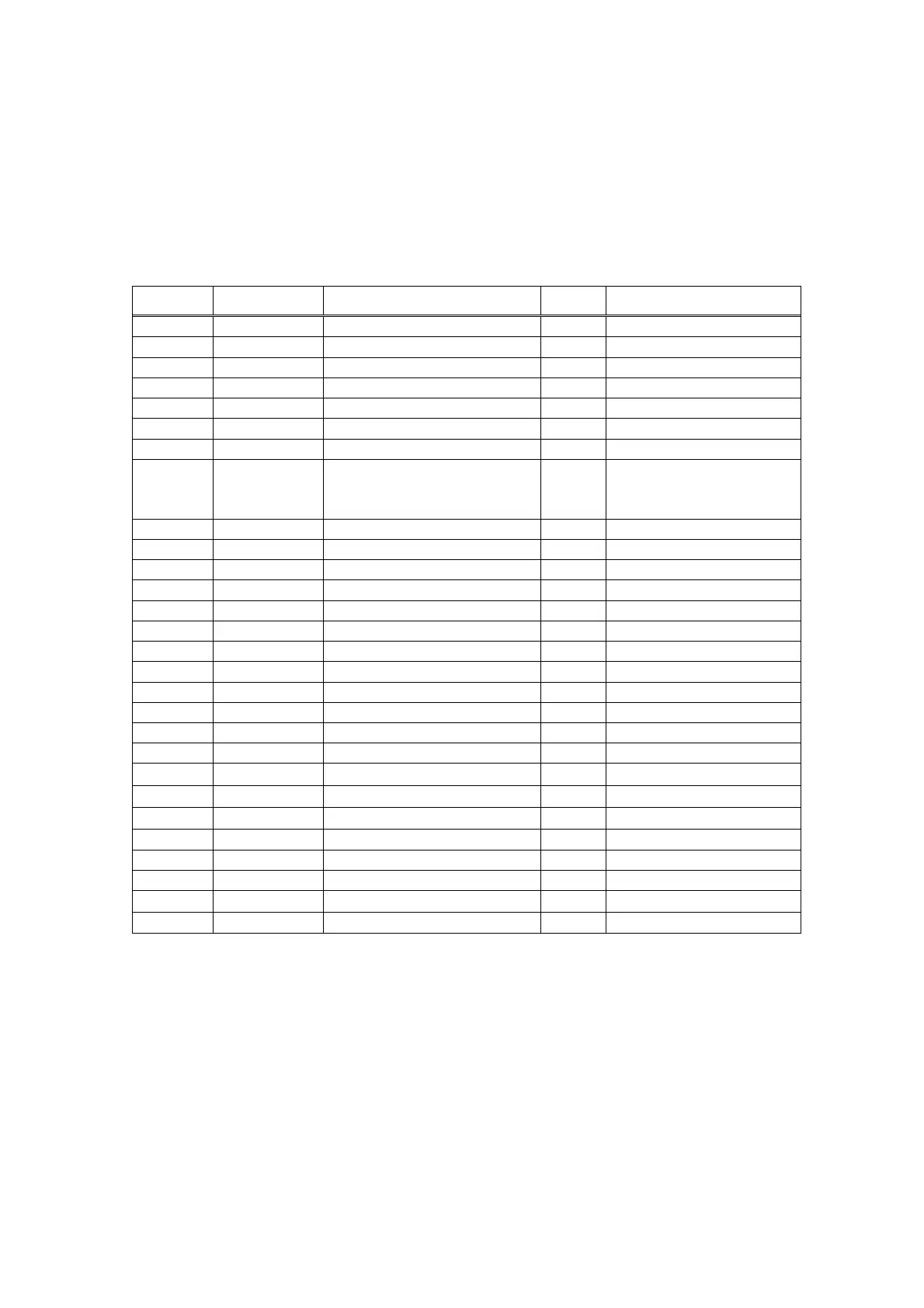
Table 7-4-1 PCR28 pin(male) connector of CSU-X1 main unit
Pin No. Signal Name Function I/O Connection
1 Reserved
2 Reserved
3 SHUTTER*1 High: Open, Low: Close Input TTL/CMOS level
4 Reserved
5 Reserved
6 Reserved
7 SYNC Sync trigger signal input Input TTL/CMOS level
8 INDEX Sync trigger signal output
Pulse width 10ms<,
300Hz-2kHz
Output TTL/CMOS level
9 Interlock Open for Interlock Input TTL/CMOS level
10 Reserved
11 Reserved
12 Reserved
13 PORT M6 port position signal Output TTL/CMOS level
14 Reserved
15 Reserved
16 Reserved
17 Reserved
18 Reserved
19 Reserved
20 Reserved
21
SYNC-
GND
22
INDEX-
GND
23
Interlock-
GND
24 Reserved
25 Reserved
26 Reserved
27
PORT-
GND
28 Reserved
*1: For the protection of shutter, maximum allowable On/Off frequency is 3Hz. If
you input faster signal, shutter may not work properly.
 Loading...