IM 12A01A02-01E 9/11
8th Edition
Model: FLEXA Series Date: April 17, 2015
Rev. Doc. No.: IFM039-A71 P. 2
Yokogawa Electric Corporation
Notes:
1. This drawing replaces the former control drawing IKE039-A12.
2. No revision to this drawing without prior approval of FM.
3. Installation must be in accordance with the National Electric Code (NFPA70), ANSI/ISA
RP12.06.01 and relevant local codes.
4. The associated apparatus must be a linear source which is FM-approved.
5. Control equipment connected to the associated apparatus must not use or generate more than
250 V a.c. r.m.s or d.c.
6. The control drawing of the associated apparatus must be followed when installing the
equipment.
7. Measuring Module 2 may not be installed. As for ISC module and SENCOM module, only one
module is permitted to be installed at a time.
8. For Division 1 / Zone 0 installation, Sensor 1 and Sensor 2 may be simple apparatus, or
intrinsically safe apparatus with the following entity parameters. For Division 2 / Zone 2
installation, they may be equipment suitable for Division 2 / Zone 2, or simple apparatus, or
nonincendive field wiring apparatus with the following nonincendive field wiring parameters.
Ui (or Vmax) ≥ Uo
Ii (or Imax) ≥ Io
Pi ≥ Po
Ci ≤ Co – Ccable
Li ≤ Lo – Lcable
9. For Division 2 / Zone 2 installation, general-purpose power supply may be used if a
wiring method suitable for Division 2, but other than nonincendive field wiring, is
taken.
10. WARNING – POTENTIAL ELECTROSTATIC CHARGING HAZARD -WHEN THE
EQUIPMENT USED IN HAZARDOUS LOCATIONS, AVOID ANY ACTION WHICH
GENERATE ELECTROSTATIC DISCHARGE SUCH AS RUBBING WITH A DRY
CLOTH.
11. WARNING – IN THE CASE WHERE THE ENCLOSURE OF THE ANALYZER IS MADE OF
ALUMINUM, IF IT IS MOUNTED IN ZONE 0, IT MUST BE INSTALLED SUCH, THAT EVEN
IN THE EVENT OF RARE INCIDENTS, IGNITION SOURCES DUE TO IMPACT AND
FRICTION SPARKS ARE EXCLUDED
12. WARNING – SUBSTITUTION OF COMPONENTS MAY IMPAIR INTRINSIC SAFETY
AND SUITABITLITY FOR DIVISION 2 / ZONE 2.
Model: FLEXA Series Date: April 17, 2015
Rev. Doc. No.: IFM039-A71 P.1
Yokogawa Electric Corporation
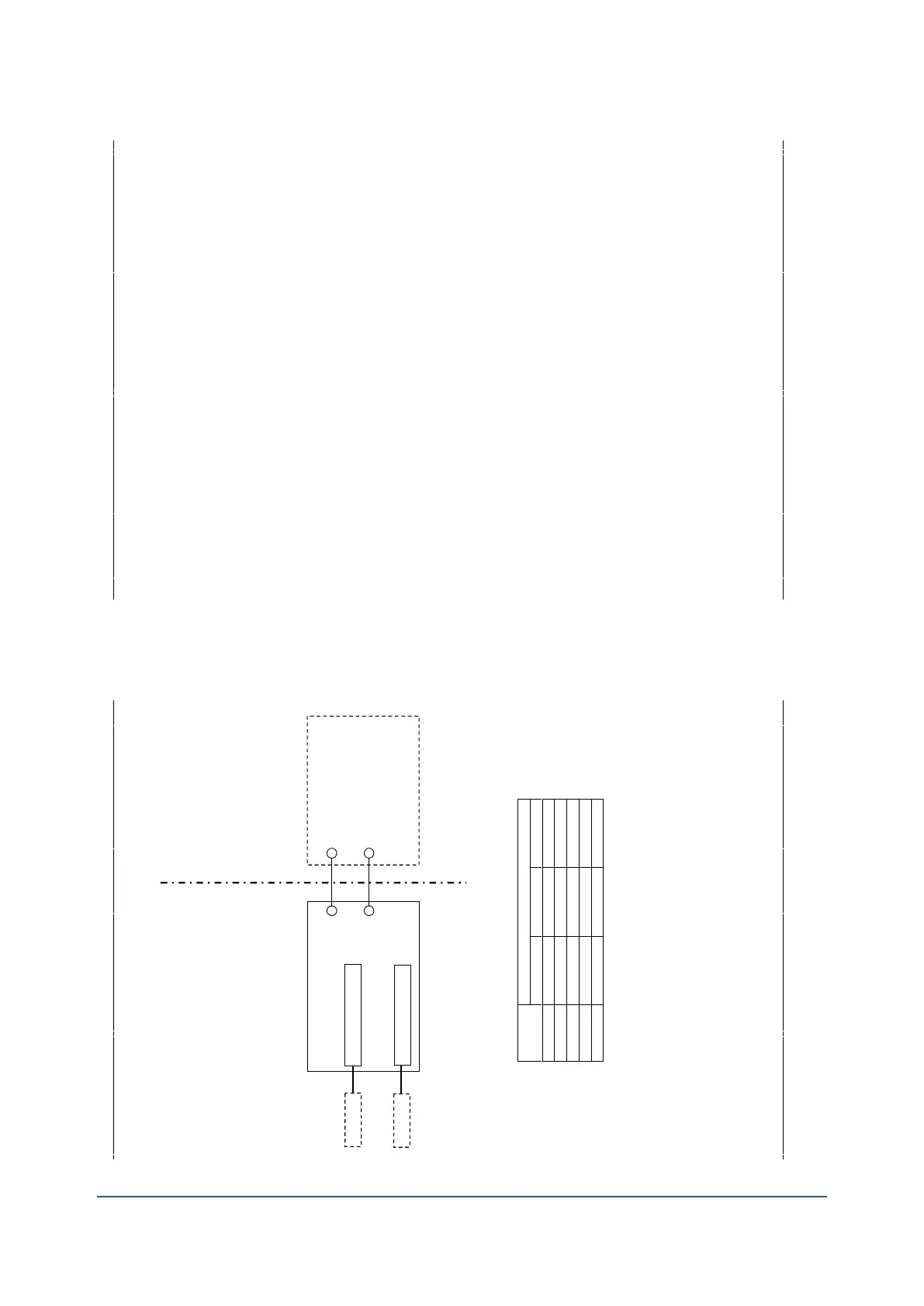
Control drawing (4–20 mA type)
Hazardous (Classified) Location
Class I, Division 1, Groups A, B, C, D, or
Class I, Zone 0, Group IIC
or
Class I, Division 2, Groups A, B, C, D, or
Class I, Zone 2, Group IIC,
Temperature Class: T4
Ui: 30 V
Ii: 100 mA (only for IS)
Pi: 0.75 W (only for IS)
Ci: 13 nF
Li: 0 mH
Measuring Module 1, 2
Associated Apparatus with
Entity Parameters or
NIFW parameters
Voc (or Uo) ≤ Ui
Isc (or Io) ≤ Ii (only for IS)
Po ≤ Pi (only for IS)
Ca (or Co) ≥ Ci + Ccable
La (or Lo) ≥ Li + Lcable
Specific condition of use
- Precautions shall be taken to minimize the risk from electrostatic discharge of non-metallic
parts and painted parts of the enclosure. When the equipment used in hazardous
avoid any action which generate electrostatic discharge such as rubbing with a dry cloth.
- In the case where the enclosure of the analyzer is made of Aluminum,
if it is mounted in
ZONE 0, it must be installed such, that even in the event of rare incidents, ignition sources due
to impact and friction sparks are excluded.