<3. OPERATION OF pH/ORP>
3-7
IM 12A01A02-01E 8th Edition : Oct. 01, 2015-00
n PH (ORP)’s zero, slope, and sensor, and Impedance
l Zero
= calibrated sensor offset in mV. Theoretically, the sensor reads 0 mV in a buffer solution of pH
7. The ZERO value indicates the condition of the sensor. The trend of ZERO drift of the sensor is
used to predict the lifetime of the sensor.
ZERO can also be displayed in pH units and then it represents the pH value where the sensor
output is 0 mV at 25ºC. Setting can be made in Commissioning → Measurement setup →
Calibration settings → Zero and Slope units.
Setting of the zero value can be made in Commissioning → Measurement setup → Calibration
settings → Zero/Slope/ITP. For details, see section 4.2.4.
l Slope
= calibrated efciency of the sensor unit as a percentage of the theoretical slope of the sensor
unit. The theoretical slope follows the NERNST equation and is 59.16 mV/pH (at 25ºC). The
SLOPE can be calibrated only after a two-point calibration in buffer solutions with a different pH
value. A low slope indicates that the sensor is not clean or is faulty.
The SLOPE can also be displayed as a mV/pH value at 25ºC if the user has dened this variable
as mV/pH in Commissioning → Measurement setup → Calibration settings → Zero and Slope
units.
Setting of the slope value can be made in Commissioning → Measurement setup → Calibration
settings → Zero/Slope/ITP. For details, see section 4.2.4.
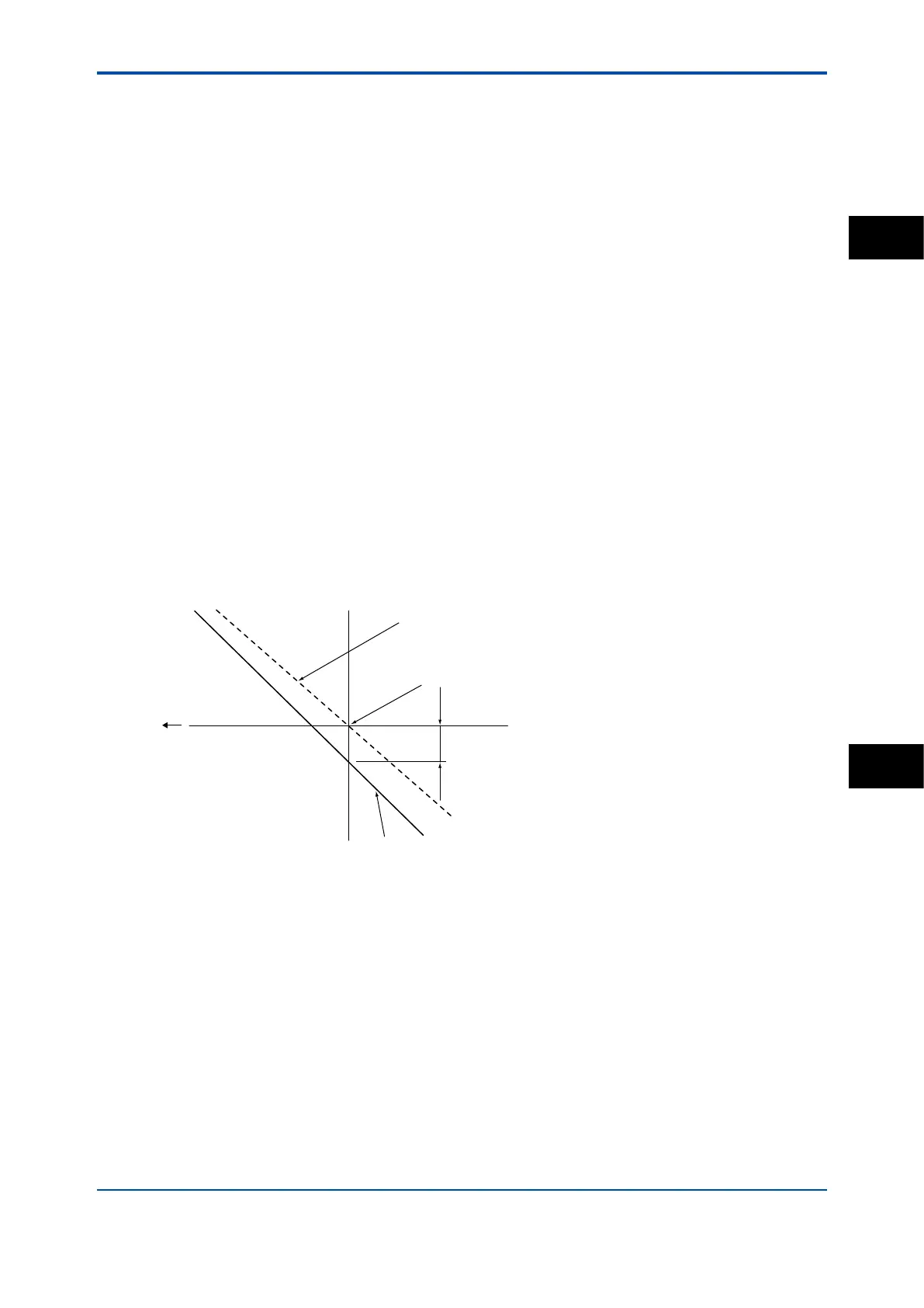
pH14
pH0
pH7, 0mV
Theoretical value
-mV
Calibration curve (slope)
Zero
F0410.ai
Figure 3.7 Zero/slope
l Sensor
Represents the electromotive force of the sensor.
l Impedance 1
For a PH sensor, “Impedance” shows electrical resistance of the glass membrane electrode. The
FLXA202/FLXA21 checks the impedance to know damage of the electrode.
For an ORP sensor, “Impedance” shows electrical resistance of metal electrode.
The FLXA202/FLXA21 checks the impedance to know the surface condition of smudge and
the snapping of sensor wires. In case of “Input Impedance setting” is “High” and the measured
input-1 impedance value is higher than 100 kΩ, the display shows “MΩ RANGE”. The measured
input-1 impedance value is lower than 100 kΩ, display shows “BAD”.
PH
3