Stamp Company : Stamp Certification Institute :
Signature : Remarks :
Model EXA PH202S
Title : Installation Drawing PH202S CSA
Number : FF1-PH202S-00 Page : 4 of 10
Revision : 5.4
YOKOGAWA EUROPE B.V.
Date : 01/07/2004
〈 Sensor(s) are a thermocouple, RTD’s, passive resistive switch devices, or is CSA entity
approved and meet connection requirements.
〈 Electrical data of the EXA PH202S-F & PH202S-P:
- Supply and output circuit::
Maximum input voltage Vmax=24 V or Maximum input voltage Vmax=17.5 V
Maximum input current Imax=250 mA Maximum input current Imax=380 mA
Maximum input power Pmax=1.2 W Maximum input power Pmax=5.32 W
Effective internal capacitance Ci=737 pF; Ef fective internal inductance Li=2.6
µH.
- Sensor input circuit:
Maximum output voltage Voc=14.4V; Maximum output current Isc=32.3 mA
Maximum allowed external capacitance Ca=600 nF
Maximum allowed external inductance La=36 mH
〈 Any CSA approved I.S. interface m ay be used that meets the following requirements:
Vmax
≤ 24 V or Vmax ≤ 17.5 V
Imax
≤ 250 mA Imax ≤ 380mA
Pmax
≤ 1.2 W Pmax ≤ 5.32 W
Ca
? 737 pF + Ccable; La ? 2.6 µH + Lcable
Installation should be in accordance with Canadian Electrical Code, Part I or CEC, Part I.
Maximum safe area voltage should not exceed 250 Vrms.
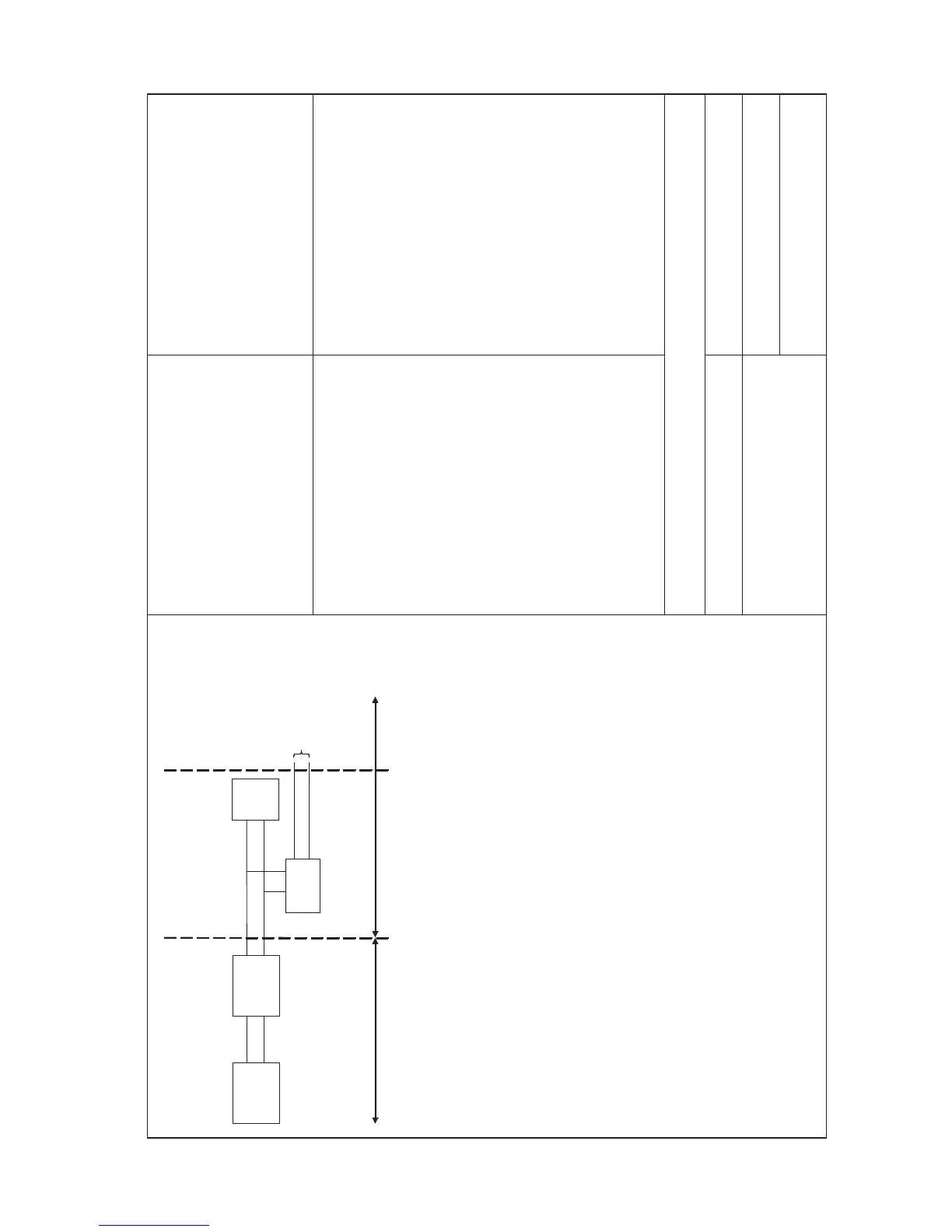
Safe area
Hazardous area
Zone 1
Zone 0 or 1
Safe area
Apparatus
I.S.
interface
I.S.
certified
Terminator
EXA
PH202S-F
& PH202S-P
Sensor
Connections
V
m
ax
= 24 V or V
max
= 17,5 V
I
max
= 250 mA I
max
= 380 mA
P
m
ax
= 1,2 W P
max
= 5,32 W
CSA Ex ia Class I, DIV. 1, Group C&D
T3C for ambient temp.
≤ 55 ϒC

 Loading...


