IM 12B6C3-E-E
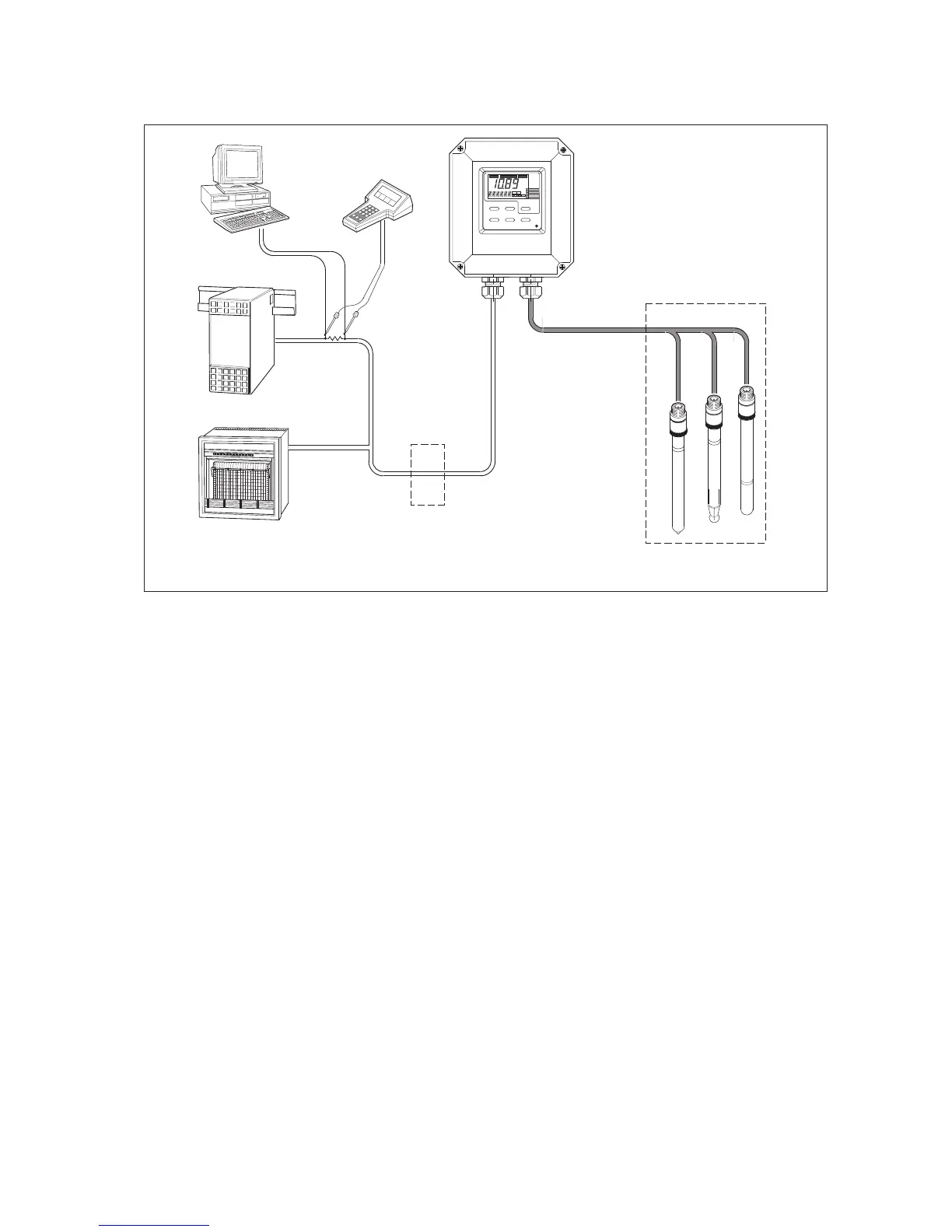
Figure 3-6. System configuration
3-3. Wiring of sensors
3-3-1. General precautions
Generally, transmission of signals from pH sensors is at a very low voltage and high impedance level. Thus
a lot of care must be taken to avoid interference. Before connecting sensor cables to the transmitter make
sure that next conditions are met:
– the sensor cables are not mounted in tracks together with high voltage and or power switching cables
– only standard coaxial electrode cables or extension cable are used
– the transmitter is mounted within the distance of the sensor cables (max. 10 m)
– the setup is kept flexible for easy insertion and retraction of the sensors in the fitting.
3-3-2. Additional precautions for installations in hazardous areas
Make sure that the total of capacitances and inductances connected to the input terminals of the EXA
PH202S do not exceed the limits given in the certificate.
This sets a limit to the cable and extensions used.
– The intrinsic safe version of the PH202S instrument can be mounted in Zone 1.
– The sensors can be installed in Zone 0 or Zone 1 if a safety barrier according to the limits given in the
system certificate is used.
– Ensure that the total of capacitances and inductances connected to the terminals of the EXA PH202S do
not exceed the limits given in the certificate of the safety barrier or distributor.
– The cable used should preferably have a BLUE colour or marking on the outside.
– Installation for (sensors in Zone 0 or 1):
Generally, the distributor with input/output isolation has no external earth connection. If there is an earth
connection on the distributor and the external connection of the transmitter is connected to “protective”
earth, the shield of the 2-wire cable may NOT be connected to “protective” earth at the distributor too.

 Loading...


