IM 12B6C3-E-E
2-1. General
A. Input specifications
: Dual high impedance inputs
(2 x 10
13
) with provision
for liquid earth connection.
Suitable for inputs from glass
or enamel pH & reference
sensors and ORP metal
electrodes.
B. Input ranges
- pH : -2 to 16 pH
- ORP : -1500 to 1500 mV
- rH : 0 to 55 rH
- Temperature : -30 ºC - 140 ºC (-20 - 300 ºF)
- 8k55 sensor : -10 ºC - 120 ºC (10 - 250 ºF)
- PTC10k : -20 ºC - 140 ºC (0 - 300 ºF)
C. Span
- pH : min 1 max 20 pH
- ORP : min 100 max 3000 mV
- rH : min 2 max 55 rH
D. Output signa• : 4-20 mA loop powered,
isolated from input,
maximum load 425 at 24 V
DC. With the possibility of
22 mA “FAIL” signal (burn up)
and 3.9 mA (burn down).
E. Temperature compensation
- Range : Automatic or manual
compensation to Nernst
equation.
Process compensation by
configurable coefficient.
Compensation for total range
of selected temperature
sensors (see B)
Adjustable ITP (Iso-thermal
point of intersection).
F. Calibration : Semi-automatic using pre-
configured NIST buffer tables
4, 7 & 9, of with user defined
buffer tables, with automatic
stability check.
Manual adjustment to grab
sample.
Slope and Asymmetry
Potential setting.
Zero point can be selected for
calibration and display instead
or As. Pot. (IEC746-2)
G. Serial communication
: Bi-directional HART® digital
communication superimposed
on the 4-20 mA signal.
H. Logbook : Software record of important
events and diagnostic data.
Available through HART
link, with key diagnostic
information available in the
display.
I. Display : Custom liquid crystal display,
with a main display of 3
1
/
2
digits 12.5 mm high.
Message display of 6
alphanumeric characters, 7
mm high.
Warning flags and units (pH
and mV).
J. Power supply : Nominal 24 volt DC loop
powered system.
- PH202G : Up to 40 volts.
- PH202S : Up to 31.5 volts.
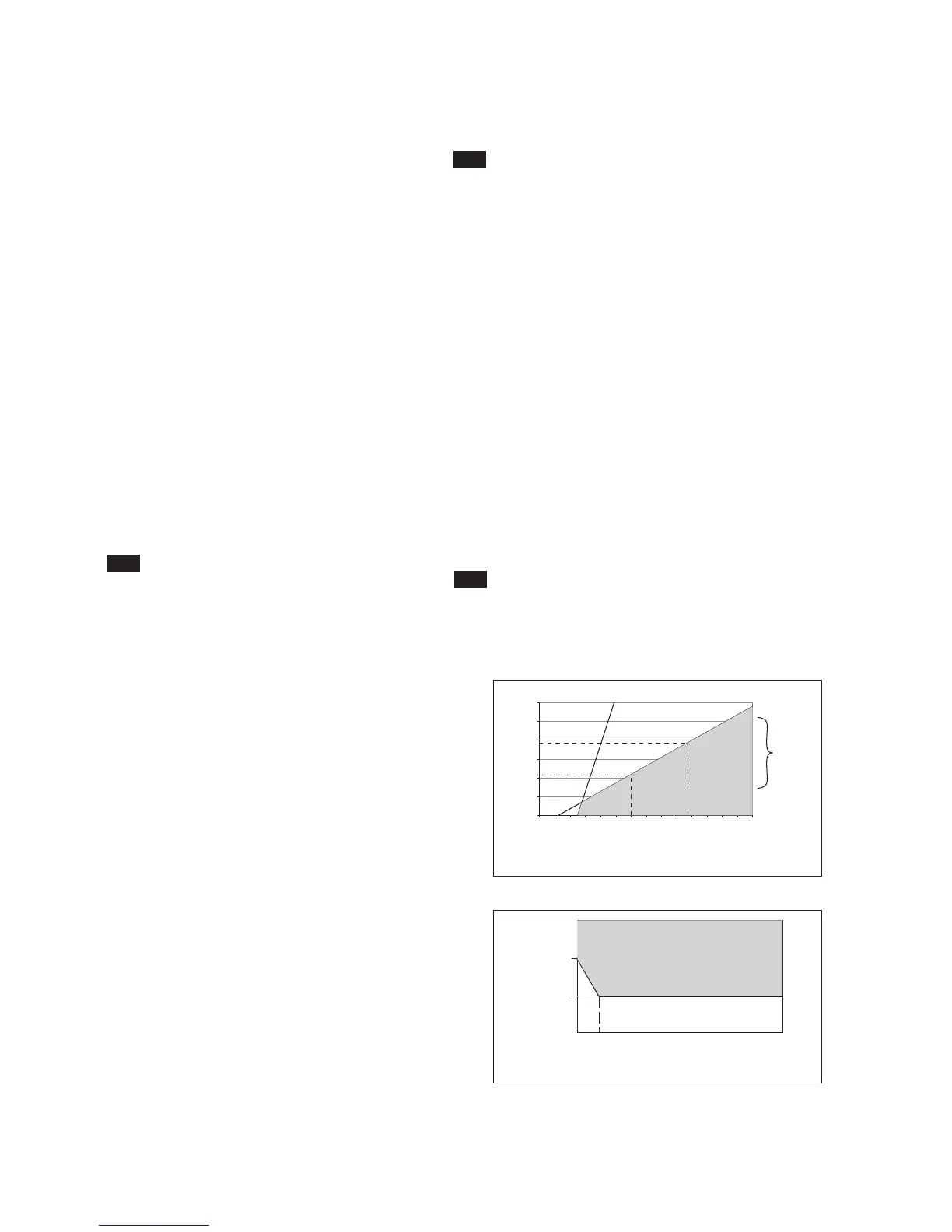
NOTE: The transmitter contains a switched power
supply. The transmitter requires a minimum
Power voltage in order to work correctly, which
is dependant on the load. Please refer to figures
2-1 and 2-2 for the correct power supply.
2. PH202 SPECIFICATIONS
Fig. 2-1. Supply voltage/ load diagram
Fig. 2-2. Minimum terminal voltage at the PH202

 Loading...


