IM 12B6C3-E-E
3-4-2. Connection of the power supply
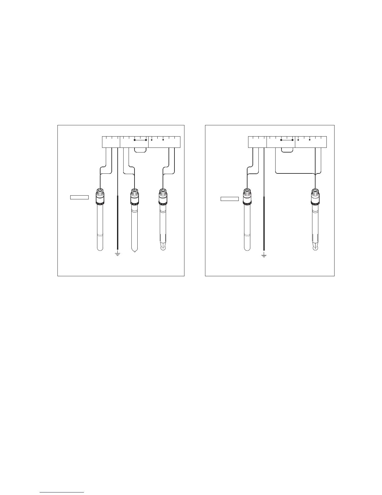
The terminal strip is accessed as was described in §3-2-1. Use the left-hand gland to insert the supply/
output cable to the transmitter. Connect the supply to the terminals marked +, - and G as is indicated in
figures 3-8 and 3-9.
3-4-3. Switching the instrument on
After all connections are made and checked, the power can be switched on from the distributor. Observe
the correct activation of the instrument at the display. If for any reason the display does not indicate a value,
consult the trouble shooting section.

 Loading...


