IM 12B6C3-E-E
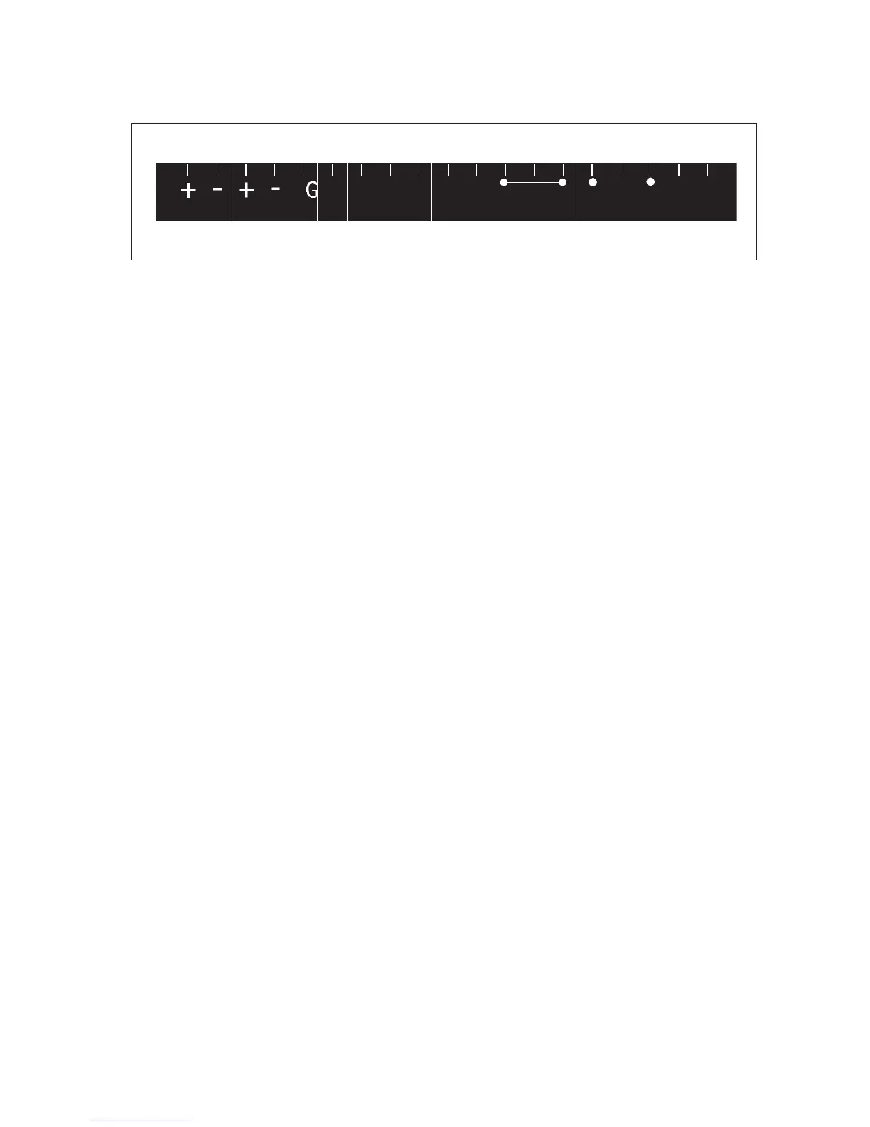
Figure 3-9. Terminal identification labels
3-6. Sensor wiring
Refer to figure 3-10, which includes drawings that outline sensor wiring.
The EXA analyzers can be used with a wide range of commercially available sensor types, both from
Yokogawa and other manufacturers. The sensor systems from Yokogawa fall into two categories; the ones
that use a fixed cable and the ones with separate cables.
To connect sensors with fixed cables, simply match the terminal numbers in the instrument with the
identification numbers in the instrument on the cable ends.
The separate sensors and cables are not numbered, but instead use a color-coding system. The electrodes
have a colored band incorporated in the label on the connection cap:
• Red for measuring electrodes (both pH and ORP)
• Yellow for reference electrodes
• Blue for combined sensors with both measuring and reference elements in the same body
• Green for temperature sensors
The recommended procedure is to color-code each end of the cables to match the sensors with the color
strips provided with each cable. This provides a quick way to identify the ends of the cables belonging to
a particular sensor when they are installed. (The procedure for fixing the identification labels is described in
detail in the instruction sheet provided with the cable.)

 Loading...


