IM 12B6C3-E-E
3-3 Installation and wiring
3-2. Preparation
Refer to figure 3-4. The power/output connections and the sensor connections should be made in
accordance with the diagram on page 3-6. The terminals are of a plug in style for ease of mounting.
To open the EXA 202 for wiring:
1. Loosen the four frontplate screws and remove the cover.
2. The terminal strip is now visible.
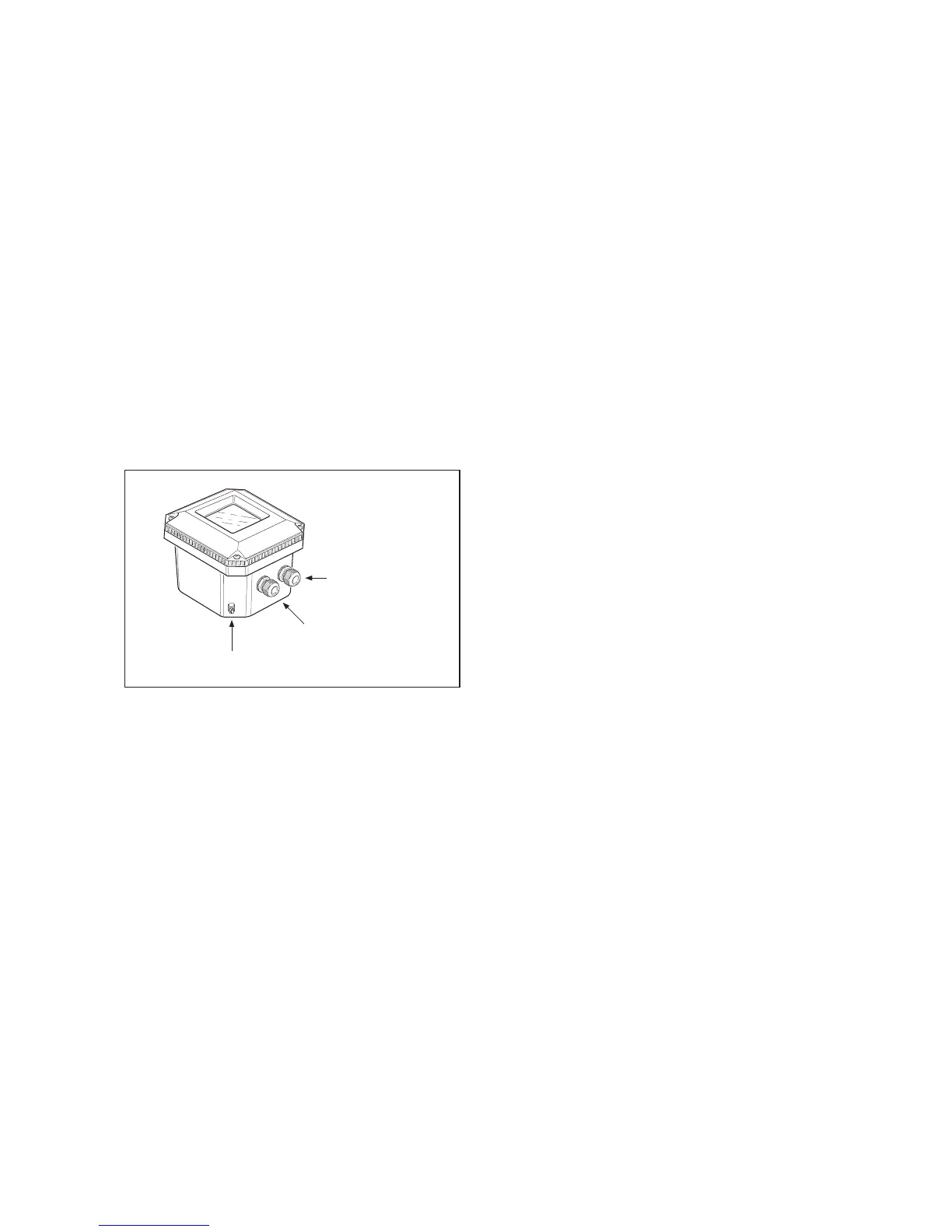
3. Connect the power supply. Use the gland on the left for this cable.
4. Connect the sensor input, using the gland on the right (see fig. 3-5). Switch on the power. Commission
the instrument as required or use the default settings.
5. Replace the cover and secure frontplate with the four screws.
6. Connect the grounding terminals tp protective earth.
7. The optional hose connection is used to guide the cables comming from an immersion fitting through
aprotective plastic tubing to the transmitter.
3-2-1. Cables, terminals and glands
The PH202 is equipped with terminals suitable for the connection of finished cables in the size range: 0.13
to 2.5 mm (26 to 14 AWG). The glands will form a tight seal on cables with an outside diameter in the
range of 7 to 12 mm (9/32 to 15/32 inches).
Figure 3-5. Glands to be used for cabling

 Loading...


