IM 12B07D02-01E
Appendix 12-7
3/3
QIS 12B07D02-21E
Table 2
Reference Temperature
(°C)
Resistance Box Resistance
(:)
Data Display
(°C)
-20 921.6 -20.0 ±0.3
+25 1097.3 +25.0 ±0.3
+130 1498.3 +130.0 ±0.3
3.5 pH Indication Check
Following Section 3.4, press the [ENT] key until the message display shows “PH.INP.” In this
state, change the simulation input as shown in Table 3 by means of the standard
voltage/current source and check the data display. The corresponding value on the data display
must be within the range shown in Table 3.
Table 3
Check Point (pH) Simulation Input (mV) Data Display (pH)
0 +414.1 0.00 ±0.01
7 0.0 7.00 ±0.01
14 -414.1 14.00 ±0.01
3.6 ORP Indication Check
Following Section 3.5, press the [ENT] key. The message display shows “ORP.INP.” In this state,
change the simulation input as shown in Table 4 by means of the standard voltage/current source
and check the data display. The corresponding value on the data display must be within the
range shown in Table 4.
Table 4
Simulation Input (mV) Data Display (mV)
-1500 -1500 ±1
0 0 ±1
+1500 +1500 ±1
Press the [ENT] key until the message display shows “READY.”
Press the [ENT] key again to end the tests.
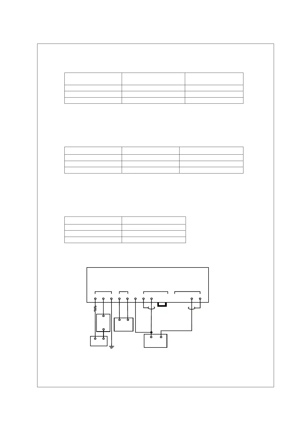
Figure 1 Testing Circuit and Test Equipment
DC source
24 V DC
Standard
Voltage Source
+
300 :
+
-
-
DC
Milli-
ammeter
Ground
-
+
Shorting bar
Decade
Resistance
Box
PH202S
SUPPLY TEMP INPUT 2 INPUT 1LE
LOW IMP
HIGH IMP
+
-
G 11 12 14 17 13 15 16

 Loading...


