IM 12B07D02-01E
Specification 2-1
2-1. General
A. Input specifications
: Dual high impedance inputs (2 x 10
12
Ω) with
provision for liquid earth connection. Suitable
for inputs from glass or enamel pH & refer-
ence sensors and ORP metal electrodes.
B. Input ranges
- pH : -2 to 16 pH
- ORP : -1500 to 1500 mV
- rH : 0 to 55 rH
- Temperature : -30ºC to 140ºC (-20 to 300ºF)
- 8k55Ω NTC sensor: -10ºC to 120ºC (10 to
250 ºF)
- 10kΩ PTC : -20ºC to 140ºC (0 to 300ºF)
C. Output ranges
- pH : min 1 max 20 pH
- ORP : min 100 max 3000 mV
- rH : min 2 max 55 rH
- Temperature : min. 25 ºC max. 200 ºC
(for 8.55kΩ NTC sensor max. 120 ºC )
D. Output signal
: 4-20 mA loop powered, isolated from input,
maximum load 425 Ω at 24 V DC. With the
possibility of 21 mA “FAIL” signal (burn up)
and 3.6 mA (burn down when HART
®
or
distributor comm. is non-used), 3.9 mA (burn
down when HART
®
or distributor comm. is
used).
E. Temperature compensation
- Range :–30 ºC to 140 ºC
(for 8.55kΩ sensor –10 ºC to 120 ºC)
Sensor types: Pt100, Pt1000, 3kΩ PTC, 5.1kΩ
PTC, 8.55kΩ NTC, 350Ω PTC,
6.8kΩ PTC, 10kΩ PTC
Automatic or manual compensation to Nernst
equation. Process compensation by configura-
ble coefficient. Adjustable ITP (Iso-thermal point
of intersection).
F. Calibration
: Semi-automatic, using tables in transmitter
for pH 4, 7 & 9 buffer solutions, or using user-
defined tables, with automatic check of meas-
urement stability.
Manual, using standard sample, by correcting
reading to value of standard.
Calibration by slope and asymmetry potential
setting. (IEC746-2)
G. Logbook
: Software record of important events and diag-
nostic data. Available through HART
®
link,
mAmA
with key diagnostic information available in the
display.
H. Serial communication
: Bi-directional HART
®
digital communication
superimposed on the 4-20 mA signal.
I. Display
: Custom liquid crystal display, with a main dis-
play of 3 1/2 digits 12.5 mm high.
Message display of 6 alphanumeric charac-
ters, 7 mm high.
Warning flags and units (pH and mV).
J. Power supply
: Nominal 24 volt DC loop powered system.
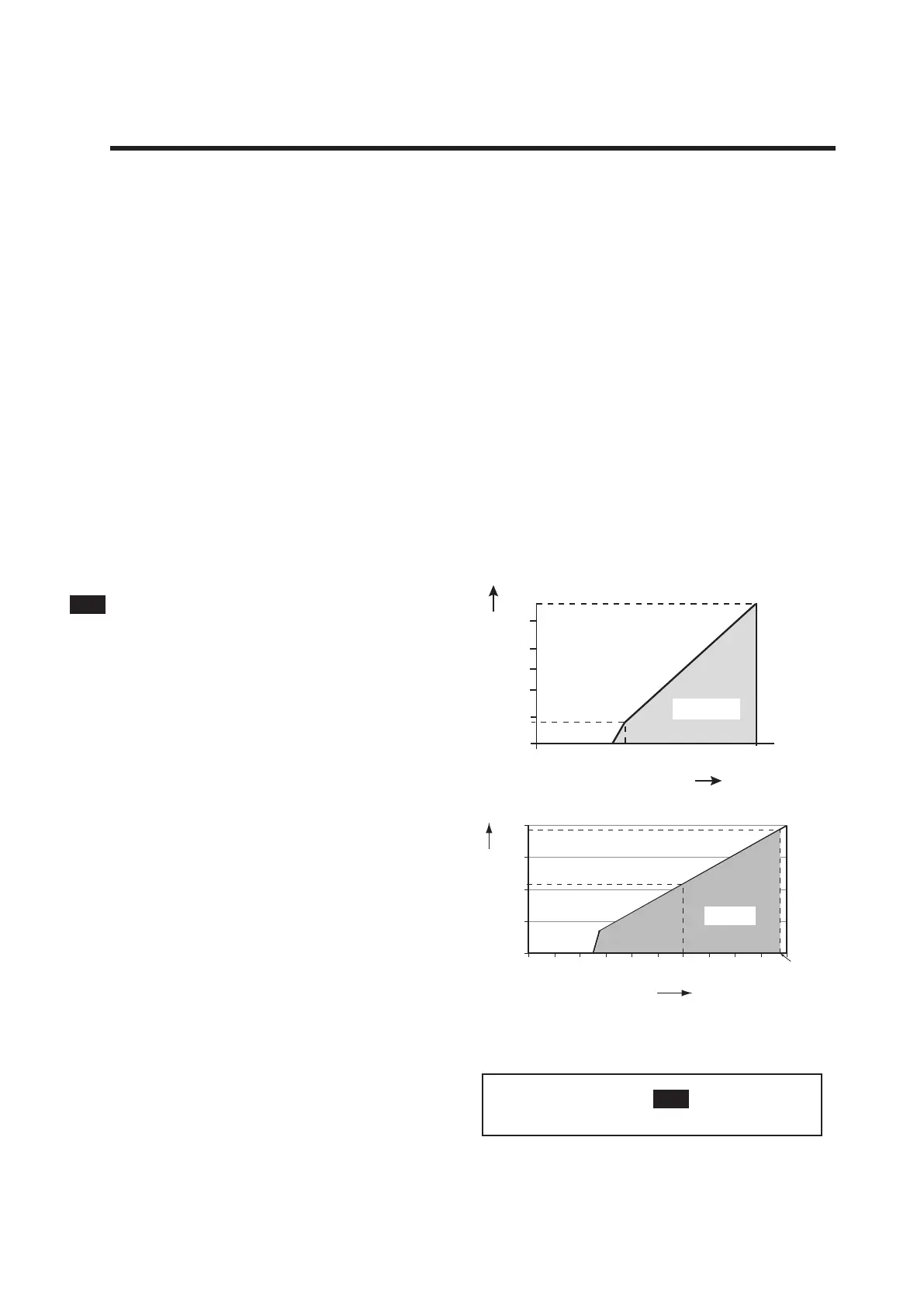
- PH202G : 17 to 40 volts, see Fig. 2-1.
- PH202S : 17 to 31.5 volts, see Fig. 2-2.
K. Maximum load resistance:
For the PH202G, see Fig. 2-1.
For the PH202S, see Fig. 2-2.
2. PH202 SPECIFICATIONS
Fig. 2-1. Supply voltage/ load diagram for the PH202G
Fig. 2-2. Minimum terminal voltage for the PH202S
0
200
400
600
800
12 16
17
20 24 28 32
425
775
Voltage (V)
Load Resistance (Ω)
31.5 V
Possible
0
0
200
180
400
600
800
1000
1150
17 18 20 25 30 35 40
F2.1E.eps
Voltage (V)
Load Resistance (Ω)
Possible
(Note) In this manual a
mA
sign appears if it
concerns the PH202G (S)-E, -C, -U, -N, -K.

 Loading...


