IM 12B07D02-01E
Specification 2-9
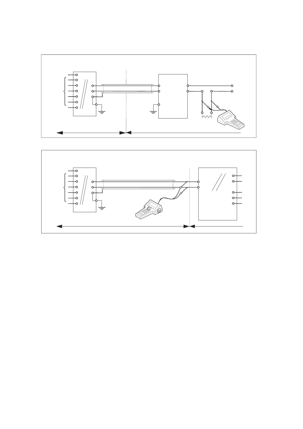
2-6. Control Drawing of PH202S mA HART
®
Specification (FM Intrinsically safe design)
Sensor(s)
terminals 11-17
Max. cablelength: 60 mtr.
Cable dia. : 3…12 mm.
Sensor(s)
terminals 11-17
Max. cablelength: 60 mtr.
Cable dia.: 3…12 mm.
Ùnclassified Location
FM Approved
Power Supply
(HART compatible)
Output
Supply
+
G
Classified Location
Unclassified Location
+
G
Functional
earth
Functional
earth
Intrinsically safe design
FM Class I, Div.1, Group ABCD, T4 for ambient temp. < 55°C
T6 for ambient temp. < 40°C
PH202S transmitter
+
-
Load
Resistance
Classified Location
Functional
earth
+
24 volts DC Nominal
Supply Voltage.
FM Approved safety barrier or
power supply
with Rint = 300 :
(HART compatible)
For electrical data:
see text below.
For electrical data:
see text below.
Intrinsically safe design
FM Class I, Div.1, Group ABCD, T4 for ambient temp. < 55°C
T6 for ambient temp. < 40°C
PH202S transmitter
Figure 1
Figure 2
・Electrical data of the PH202S.
-Supply circuit (terminals + and -):
Maximum input voltage Vmax = 31.5 V. Maximum input current Imax = 100 mA.
Maximum input power Pmax = 1.2 W.
Effective internal capacitance Ci = 22 nF. Effective internal inductance Li = 35 PH.
- Sensor input circuit (terminals 11 through 17):
Maximum output voltage Vt = 14.4 V. Maximum output current It = 32.3 mA.
Maximum allowed external capacitance Ca = 600 nF.
Maximum allowed external inductance La = 34 mH
・If Hand Held Terminal (HHT) is not connected to the power supply lines of the PH202S
(see figure 1):
Any FM Approved barrier or power supply may be used that meets the following requirements.
Voc or Vt d 31.5 V ; Isc or It d 100 mA; Ca t 22nF + Ccable ; La t 35PH + Lcable
If HHT is connected to the power supply lines of the PH202S (see figure 2):
The Hand Held Terminal must be FM Approved. Refer to the manufacturers control drawing of
the HHT and the barrier/power supply to determine the cable parameters.
(Voc or Vt ) + VHHT d 31.5 V; (Isc or It ) + IHHT d 100 mA;
Ca t 22nF + Ccable+ CHHT ; La t 35PH + Lcable+ LHHT
When installing this equipment, follow the manufacturer’s installation drawing.
Installation should be in accordance with ANSI/ISA RP 12.06.01 “Installation of Intrinsically Safe
Systems for Hazardous (Classified) Locations” and the National Electrical Code (ANSI/NFPA 70).
Control equipment connected to the barrier/power supply must not use or generate more than
250 Vrms or Vdc.
・Resistance between Intrinsically Safe Ground and earth ground must be less than 1.0 Ohm.
・In case of using cable glands in Outdoor location, they shall be UV rated or made of metal.
WARNING
- Substitution of components may impair Intrinsic Safety
- To prevent ignition of flammable or combustible atmospheres, disconnect power before servicing
or read, understand and adhere to the manufacturer’s’live maintenance procedures.
Application Doc. No.: IKE024-A10 P.4-1 to P.4-2

 Loading...


