IM 12B07D02-01E
2-14 Specification
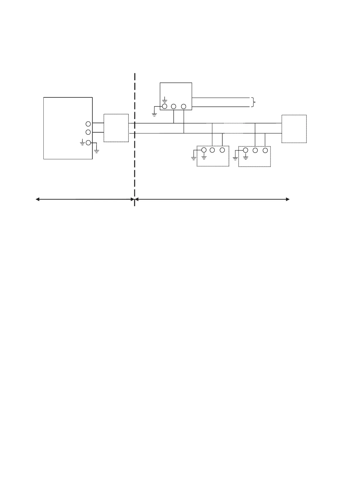
2-11. Control Drawing of PH202S FF/PB Specification (FM Intrinsically safe Entity).
Unclassified Location
Classified Location
Division 1
FM Approved
barrier
Voc (Vt) d 24 V
Ioc (It) d 250 mA
Poc (Pt) d 1.2 W
Ca t 220pF+ Ccable
La t 0 H + Lcable
Sensor
Connections
Max. cablelength: 60 mtr.
Cable dia. : 3…12 mm.
FM Class I, DIV. 1, Group ABCD
T4 for ambient temp. d 55 qC
-
+
I.S.
certified
Terminator
I.S.
certified
Terminator
PH202S-F
or PH202S-P
Transmitter
Transmitter
-
+
Sensor
Connections
-
+
-
+
x Sensor(s) are of a passive type to be regarded as 'simple apparatus', devices which neither
store nor generate voltages over 1.5 V, currents over 0.1 A, power over 25 mW or energy over
20 PJ, or are FM Approvals entity approved and meet connection requirements.
x Electrical data of the PH202S-F & PH202S-P:
- Supply circuit:
Maximum input voltage Vmax = 24 V
Maximum input current Imax = 250 mA
Maximum input power Pi=1.2 W
Effective internal capacitance Ci = 220 pF;
Effective internal inductance Li = 0 PH.
- Sensor input circuit:
Maximum output voltage Vt = 14.4 V;
Maximum output current It = 32.3 mA
Maximum allowed external capacitance Ca = 600 nF
Maximum allowed external inductance La = 34 mH
x Any FM Approved barrier may be used that meets the following requirements:
Voc or Vt d 24 V
Ioc or It d 250 mA
Poc or Pt d 1.2 W
Ca t 220 pF + Ccable; La t 0
H + Lcable
When installing this equipment, follow the manufacturer’s installation drawing.
Installation should be in accordance with ANSI/ISA RP 12.06.01 “Installation of Intrinsically
Safe Systems for Hazardous (Classified) Locations” and the National Electrical Code
(ANSI/NFPA 70).
Associated apparatus connected to the barrier must not use or generate more than
250 Vrms or Vdc.
x Resistance between Intrinsically Safe Ground and earth ground must be less than 1.0 Ohm.
x
In case of using cable glands in Outdoor location, they shall be UV rated or made of metal.

 Loading...


