IM 12B07D02-01E
3-6 Installation and wiring
3-4-2. Connection of the power supply
The terminal strip is accessed as was described in §3-2-1. Use the left-hand gland to insert the supply/
output cable to the transmitter. Connect the supply to the terminals marked +, - and G as is indicated in
figures 3-8 and 3-9.
3-4-3. Switching the instrument on
After all connections are made and checked, the power can be switched on from the distributor. Observe
the correct activation of the instrument at the display. If for any reason the display does not indicate a
value, consult the trouble shooting section.
Red
ref
pH/ORP
temp.
Green
Yellow
Colour code
rd bl
rd
bl
bk
wt
=
=
=
=
red
blue
black
white
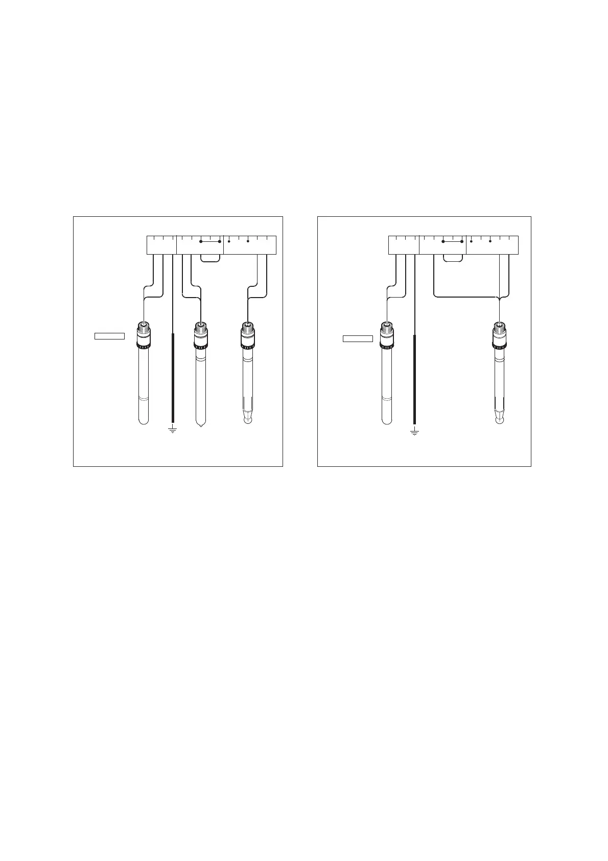
11 12 14 17 13 15 16H I G H I M PLOW IM P
TEMP LE INPUT 2 INPUT 1
rd bl
SINGLE
ELECTRODES
Blue
Combi
pH/Ref
Combi
Orp/Ref
temp.
Green
Colour code
COMBINED
ELECTRODES
rd
bk
11 12 14 17 13 15 16H I G H I M PLOW IM P
TEMP LE INPUT 2 INPUT 1
wtbl
bl
rd
bk
bl rd
rd
bl
bk
wt
=
=
=
=
red
blue
black
white
link
link
Fig. 3-7. Connection diagrams
ORP/Ref

 Loading...


