IM 12B07D02-01E
2-8 Specification
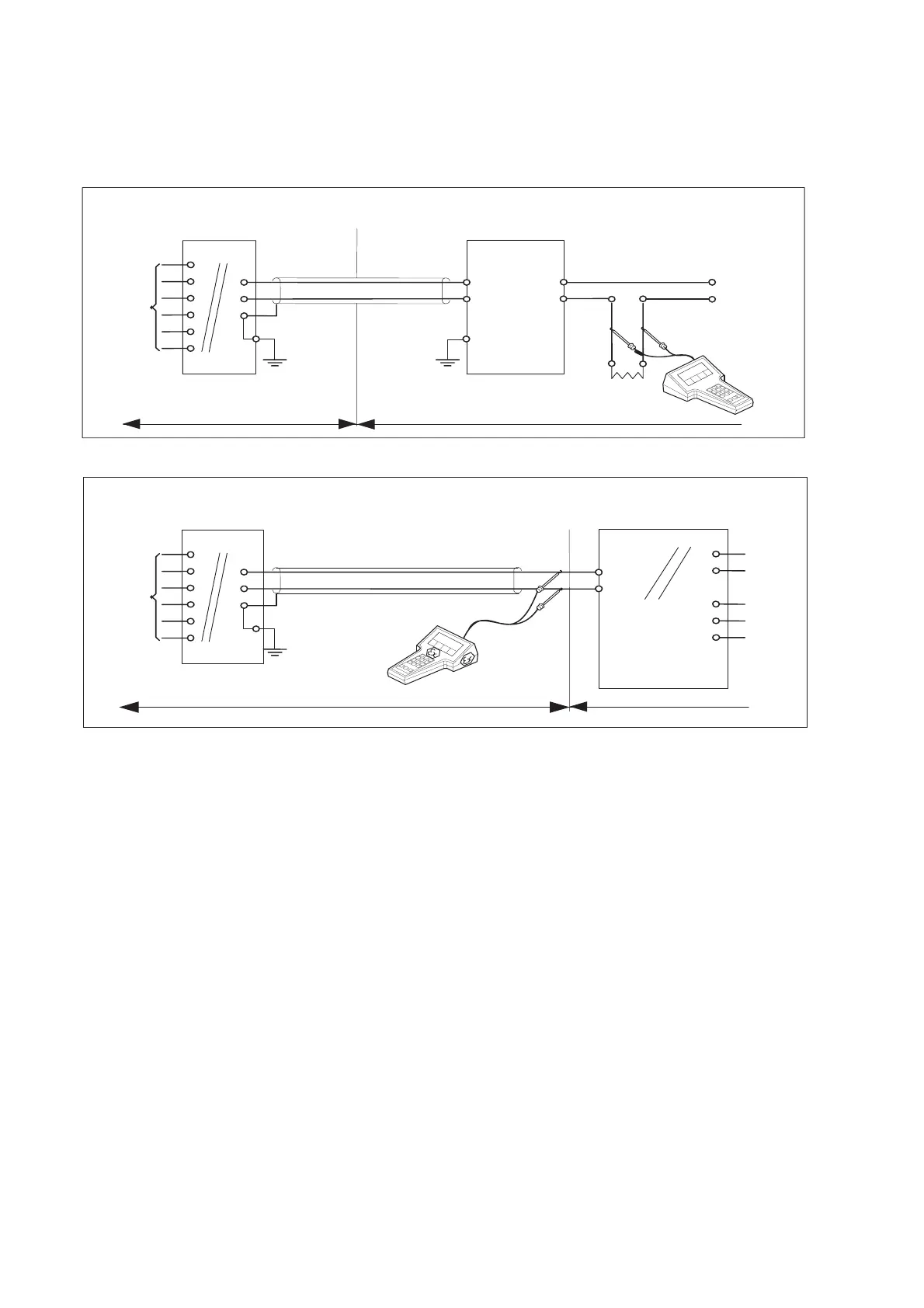
2-5. Control Drawing of PH202S mA HART
®
Specification (ATEX)
PH202S
(pH/ORP-transmitter)
Safe area
Uo = 31.5 Volt DC
Io = 100 mA
Po = 1.2 Watt
EEx ia or ib Certified Repeater
Power Supply
(HART Compatible)
Output
Supply
SENSOR(S)
terminals 11-17
+
G
SENSOR(S)
terminals 11-17
Hazardous area Safe area
+
G
Functional
earth
Functional
earth
Intrinsically safe design
CENELEC standard EEX ia IIC: T4 for ambient temp. < 55°C
T6 for ambient temp. < 40°C
Certificate nr. KEMA 06ATEX0218 X
PH202S
+
Load
Resistance
EEx ia or ib
Certified safety barrier or power
with Rint=300
:
Io = 100 mA
Uo = 31.5 Volt DC
Hazardous area
Functional
earth
+
24 volts DC Nominal
Supply Voltage.
Intrinsically safe design
CENELEC standard EEx ia IIC: T4 for ambient temp. < 55°C
T6 for ambient temp.< 40°C
Certificate nr. KEMA 06ATEX0218 X
(HART compatible)
(pH/ORP-transmitter)
Zone 0 or 1
Zone 0 or 1
・ Sensor(s) are of a passive type to be regarded as ‘simple apparatus’.
・ Electrical data of the PH202S.
- Supply and output circuit (terminals + and -):
Maximum input voltage U
i
= 31.5 V. Maximum input current I
i
= 100 mA.
Maximum input power P
i
= 1.2 W.
Effective internal capacitance C
i
= 22 nF.
Effective internal inductance L
i
= 35 PH.
- Sensor input circuit (terminals 11 through 17):
Maximum output voltage U
o
= 14.4 V. Maximum output current I
o
= 32.3 mA.
Maximum allowed external capacitance Co = 600 nF. (for PH202S-E,-C,-U),
Co = 3.5 PF (for PH202S-N).
Maximum allowed external inductance Lo = 34 mH (for PH202S-E,-C,-U),
Lo = 76 mH (for PH202S-N).
・ Barriers and power supply specification must not exceed the maximum values as shown
in the diagram above. These safety descriptions cover most of the commonly used
industry standard barriers, isolators and power supplies.
・ The safety barrier shall be certified by notify body.
・ Installation should be in accordance with local installation requirements.
・ If use ordinary wirings, the general purpose equipment must have Nonincendive
Field Wiring terminal approved.
・The Hand Held Communicator must be of a ATEX certified intrinsically safe type in case
it is used on the intrinsically safe circuit in the hazardous area or of a ATEX certified
non-incendive type in case it is used in the non-incendive circuit in the hazardous area.

 Loading...


