Table 5.5.1-2 List of Communication Cables (T
able continued)
Model Cable Name Remarks
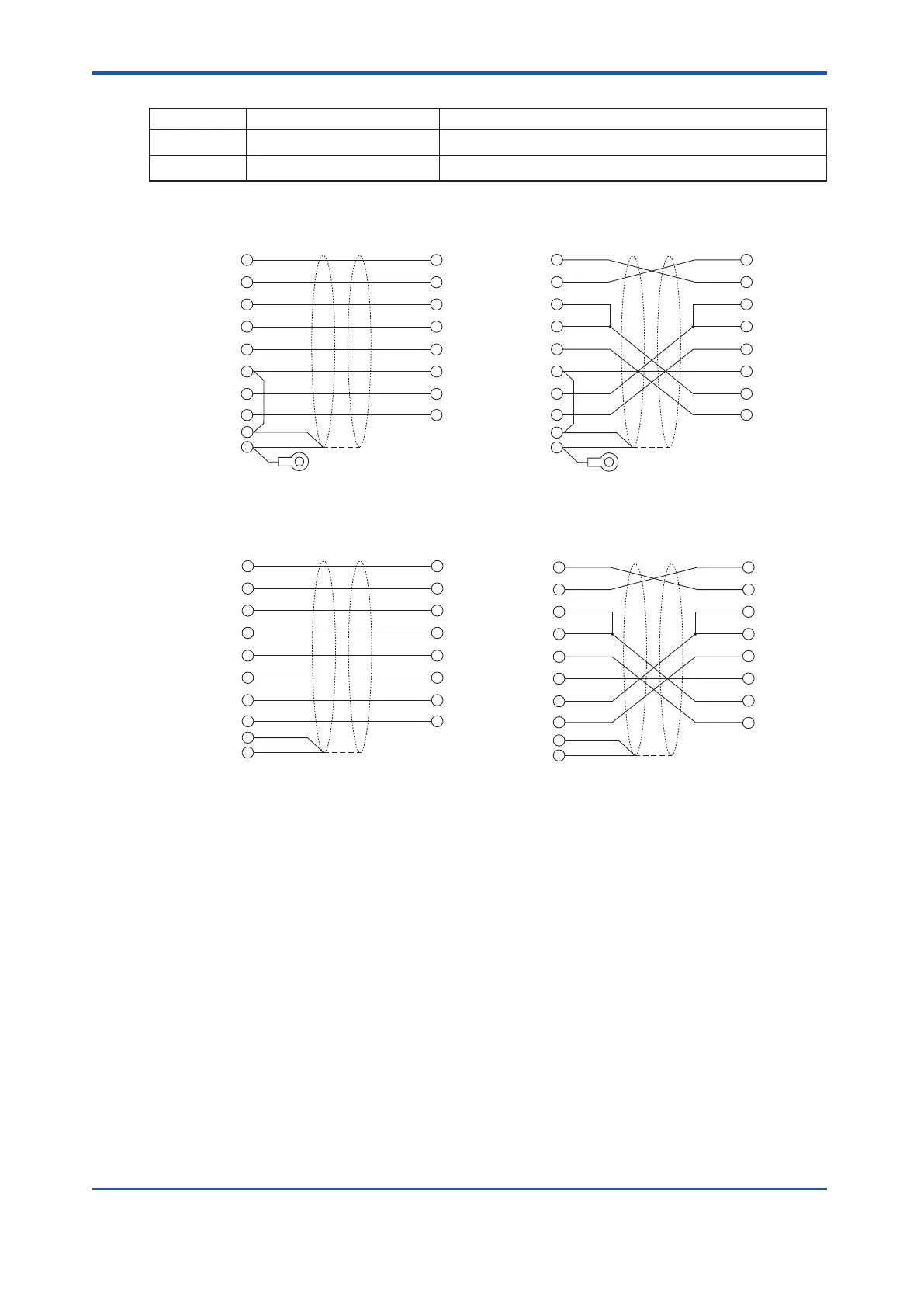
AKB135 RS-232C Modem cable Between ALR111 to modem (9-25pin)
AKB136 RS-232C Null modem cable Between ALR111 to RS-232C equipment (9-25pin)
AKB136
CN1
PIN No.
External device side
2
3
4
5
6
7
8
20
SD
RD
RS
CS
DR
SG
CD
ER
SD
RD
RS
CS
DR
SG
CD
ER
CN2
PIN No.
3
2
7
8
6
5
1
4
ALR side
1
FG
Shield
Connector shell
External device side
CN1
PIN No.
2
3
4
5
6
7
8
20
SD
RD
RS
CS
DR
SG
CD
ER
SD
RD
RS
CS
DR
SG
CD
ER
CN2
PIN No.
3
2
7
8
6
5
1
4
AKB135
ALR side
1
FG
Shield
Connector shell
External device side
AKB132
CN1
PIN No.
2
3
4
5
6
7
8
20
SD
RD
RS
CS
DR
SG
CD
ER
SD
RD
RS
CS
DR
SG
CD
ER
CN2
PIN No.
ALR side
1
FG
Shield
Connector shell
3
2
7
8
6
5
1
4
External device side
CN1
PIN No.
2
3
4
5
6
7
8
20
SD
RD
RS
CS
DR
SG
CD
ER
SD
RD
RS
CS
DR
SG
CD
ER
CN2
PIN No.
AKB131
ALR side
3
2
7
8
6
5
1
4
1
FG
Shield
Connector shell
Figure 5.5.1-5 Internal Connection of the RS-232C Interface Cable
n
Communication Module Signal Circuits
The ALR1
11 communication module effectively insulate the communication circuit signal lines,
so that the noises from the external device AC line, frame ground (FG) connecting cables and
communication cables do not flow into the safety control station. For this reason, it is neces-
sary that cable shielding wires shall be connected to the FG at the external device side.
Also at the external device side, that FG and signal ground (SG) need to be connected to
each other, to keep the same potential between them.
n
ALR111 FG Connection
The ALR111 communication module effectively insulate the RS-232C interface circuit, so that
the noises from the external device side do not flow into the safety control station, thereby im-
proving noise resistance. To use this function effectively, satisfy the following requirements:
<5.5 Connection of Communication Modules > 5-38
IM 32Q06C10-31E 4th Edition : Jan.30,2015-00
 Loading...
