• Be sure to ground the FG at the external device. Ground the grounding terminal to the
protective grounding system.
•
Connect the FG to the SG of the RS-232C circuit (pin No. 7 for D-sub25, and pin No. 5
for D-sub9) at the external device.
• Ground the cable shielding wires at the external device side.
• If the signal cable is prepared by users, make sure the cable is the type of twisted pair
cable in which a signal wire and a ground wire are paired.
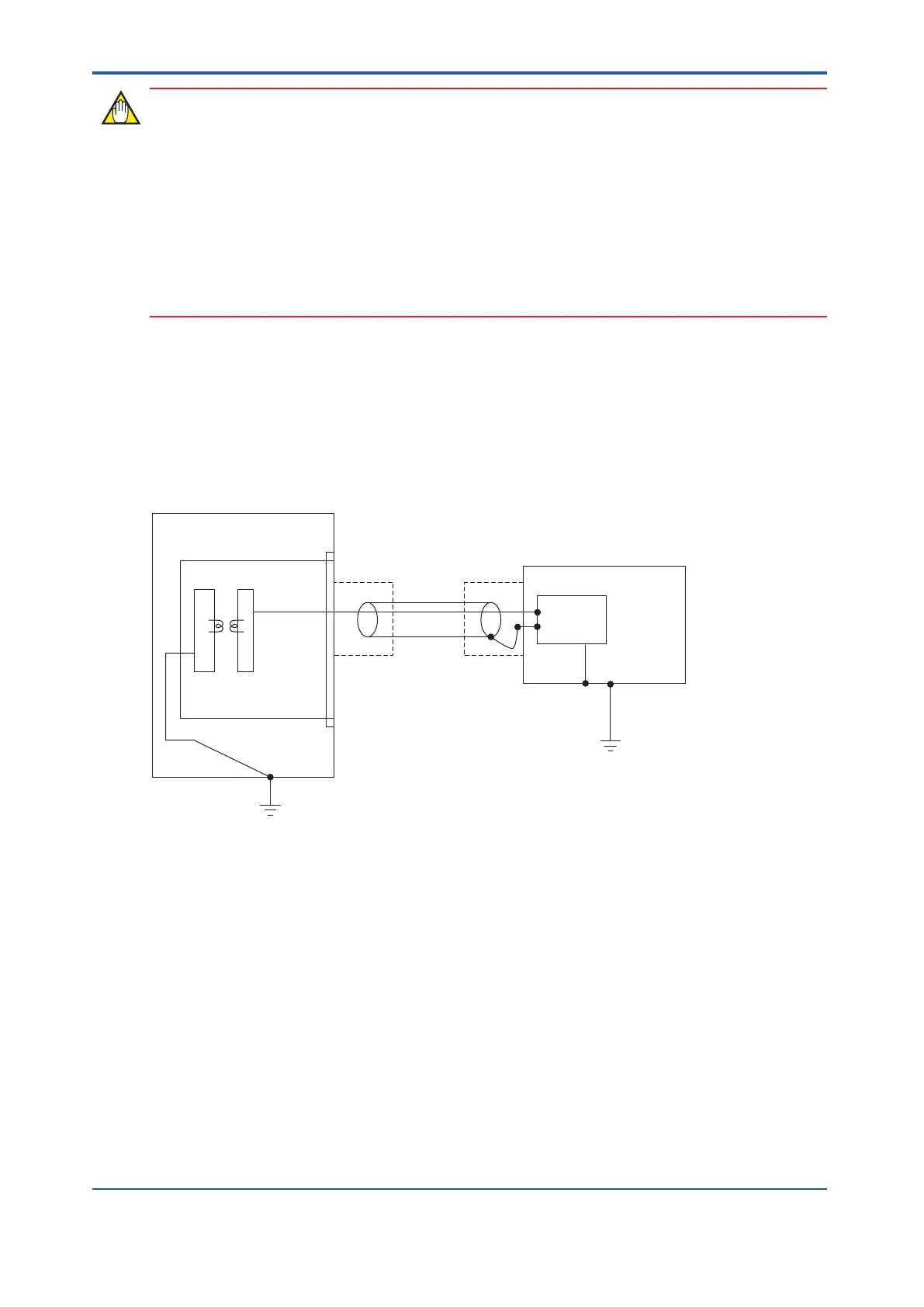
Connect the shielding wires of the RS-232C communications cable to the FG at the external
device as follows:
Ground the FG at the external device. Ground the grounding terminal to the protective
grounding system.
Check that the FG (pin No. 1 for D-sub25) and the SG (pin No. 7 for D-sub25) are connected
to each other at the RS-232C communications connector on the external device side. Also,
check that the FG is connected to the grounding terminal at the external device.
Cabinet
ALR111 module
SG1 SG2
5
7
1
AKB135 cable (Modem cable) or
AKB136 cable (Null modem cable)
Circuit
Shielding wires should
be connected to the FG
at the subsystem side.
External device
D-sub25 side
FG (Grounding Terminal)
Protective grounding system
Protective grounding system
Figure 5.5.1-6 FG Connection
n
AKB136 Cable Connection
Usually in the external devices, as shown in the following figure, SG and FG are short-circuit-
ed by a jumper-pin (J1) (see the figure bellow) upon shipment. (If it is not, short-circuit J1.) T
o
meet the above requirement, the FG and SG may be connected directly.
<5.5 Connection of Communication Modules > 5-39
IM 32Q06C10-31E 4th Edition : Jan.30,2015-00
 Loading...
