l
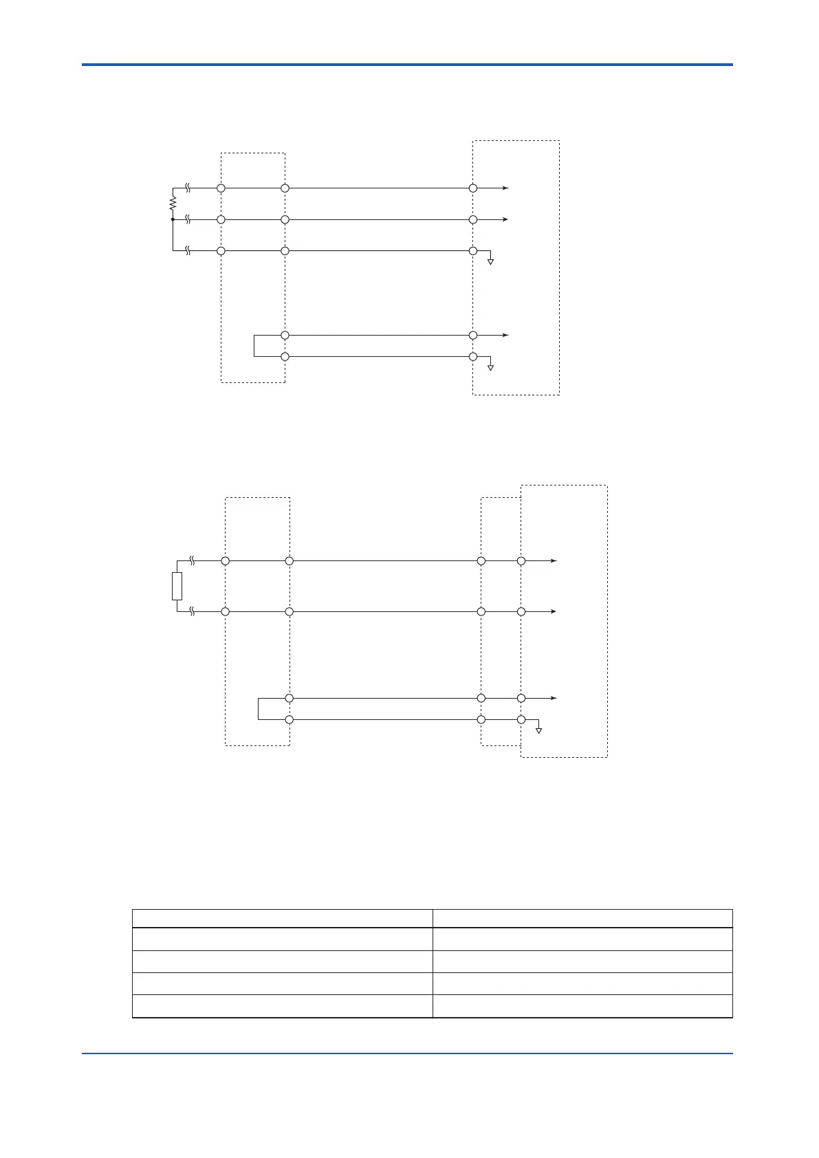
Analog Input Module SAR145
INnA INnA
CBSE
CBSE
CBSE
INnA
INnB INnB
INnB
CBSE
CBSE
RTD
INnC INnC
Analog Input Module
Terminal board
n : channel number
Signal cable
Figure 5.6-4 SAR145 Circuit Diagram
l
Analog Output Module : SAI533
Outn+
Outn-
Outn+
Outn-
CBSE
CBSE
CBSE
CBSE
CBSE
Outn+
Outn-
Analog Output module
Signal cable
interface adapter
Load
Signal cable
Terminal board
n : channel number
Figure 5.6-5 SAI533 Circuit Diagram
n
Digital Input/Output Modules
The following table shows the relationship between digital input/output modules and terminal
boards.
Table 5.6-2 Relationship Between Digital Input/Output Modules and Terminal Boards
Digital input/output module (type) Connectable terminal board (type)
SDV144 SED4D/SBD4D
SDV521 SED2D/SBD2D
SDV526 SWD2D
SDV531 SED4D/SBD3D
Continues on the next page
<5.6 Circuit Diagrams of Input/Output Modules > 5-49
IM 32Q06C10-31E 4th Edition : Jan.30,2015-00
 Loading...
