n
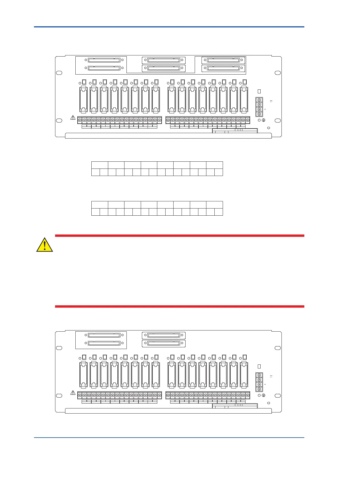
SRM53D T
erminal Numbers and Signal Names
CN1
CN2
CN3
CN4
CN5
CN6
TM1
FUSE
1 2 3 4 5 6 7 8 9 10 11 12 13 14 15 16
TM2
TM3
24V
DC
+
Figure 8.3.3-2 SRM53D Relay Board
1
A B
2
A B
3
A B
4
A B
5
A B
6
A B
7
A B
8
OUT1 Signal Name
TM1
Terminal No.
OUT2 OUT3 OUT4 OUT5 OUT6 OUT7 OUT8
A B
1
A B
2
A B
3
A B
4
A B
5
A B
6
A B
7
A B
8
OUT1 Signal Name
TM2
Terminal No.
OUT2 OUT3 OUT4 OUT5 OUT6 OUT7 OUT8
A B
Figure 8.3.3-3 SRM53D Terminal Numbers and Signal Names
• The “+” and “-” of TM3 terminals are used for connecting the power supply.
•
Before wiring is started, the protective cover for the terminals needs to be removed. And
the cover should be put back after the wiring is completed.
• It is recommended to place mediate switches or breakers in the power supply wirings so
that the power supply of each circuit can be shutoff individually during maintenance.
n
SRM54D T
erminal Numbers and Signal Names
CN1
CN2
CN3
CN4
TM1
FUSE
1 2 3 4 5 6 7 8 9 10 11 12 13 14 15 16
TM2
TM3
24V
DC
+
Figure 8.3.3-4 SRM54D Relay Board
<8.3 Cable Connection > 8-12
IM 32Q06C10-31E 4th Edition : Jan.30,2015-00
 Loading...
