1
A B
2
A B
3
A B
4
A B
5
A B
6
A B
7
A B
8
OUT1 Signal Name
TM1
Terminal No.
OUT2 OUT3 OUT4 OUT5 OUT6 OUT7 OUT8
A B
9
A B
10
A B
11
A B
12
A B
13
A B
14
A B
15
A B
16
OUT9
Signal Name
TM2
Terminal No.
OUT10 OUT11 OUT12 OUT13 OUT14 OUT15 OUT16
A B
Figure 8.3.3-5 SRM54D Terminal Numbers and Signal Names
• The “+” and “-” of TM3 terminals are used for connecting the power supply.
• Before wiring is started, the protective cover for the terminals needs to be removed. And
the cover should be put back after the wiring is completed.
• It is recommended to place mediate switches or breakers in the power supply wirings so
that the power supply of each circuit can be shutoff individually during maintenance.
n
SBM54D T
erminal Numbers and Signal Names
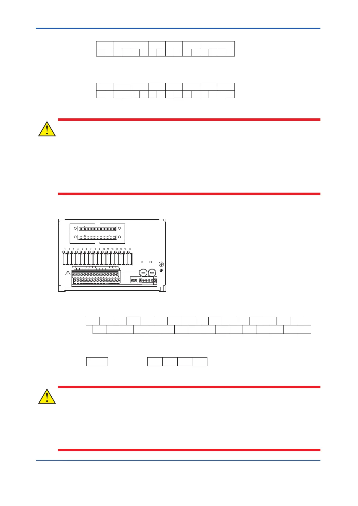
CN1
CN2
POWER1 POWER2
FUSE1
250V T 10A
FUSE2
250V T 10A
READY
1A
1 2 3 4 5 6 7 8 9 10 11 12 13 14 15 16
2A 3A 4A 5A 6A 7A 8A
1B 2B 3B 4B 5B 6B 7B 8B
9A 10A 11A 12A 13A 14A 15A 16A
9B 10B 11B 12B 13B 14B 15B 16B
Figure 8.3.3-6 SBM54D relay board
1A 2A 3A 4A 5A 6A 7A 8A 9A 10A 11A 12A 13A 14A 15A 16A
OUT1 OUT2 OUT3 OUT4 OUT5 OUT6 OUT7 OUT8 OUT9 OUT10 OUT11 OUT12 OUT13 OUT14 OUT15 OUT16
COM1 COM2 COM3 COM4 COM5 COM6 COM7 COM8 COM9 COM10 COM11 COM12 COM13 COM14 COM15 COM16
1B 2B 3B 4B 5B 6B 7B 8B 9B 10B 11B 12B 13B 14B 15B 16B
24V DC COM 24V DC COM
1+ 1- 2+ 2-
READY
READY
Signal Name
Signal Name
Terminal No.
Signal Name
Terminal No.
Signal Name
Terminal No.
Figure 8.3.3-7 SBM54D Terminal Numbers and Signal Names
• You can use dual power supply. The "1+" "1-" and "2+" "2-" of TM3 terminals are used for
connecting the power supply
.
• It is recommended to place mediate switches or breakers in the power supply wirings so
that the power supply of each circuit can be shutoff individually during maintenance.
<8.3 Cable Connection > 8-13
IM 32Q06C10-31E 4th Edition : Jan.30,2015-00
 Loading...
