SEE
ALSO
For more information about SYS_DIAG function block, refer to:
C10.6, “SYS_DIAG (diagnostic information output)” in Safety Control Station Reference (IM
32Q03B10-31E)
n
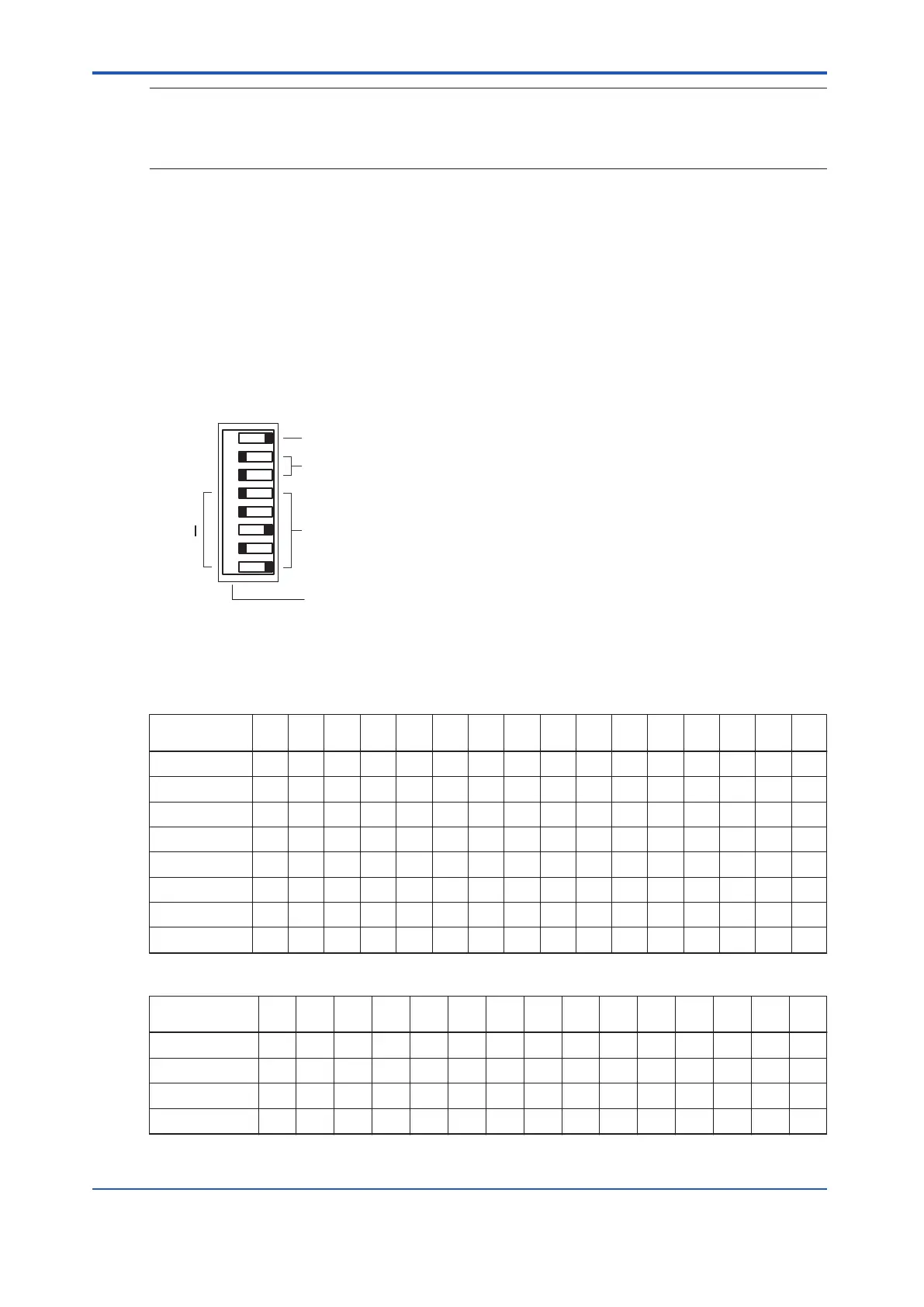
Setting the Domain Number
A domain stands for a range of stations in a network connected by control bus. Set the do-
main number in the range of 1 to 31. T
o set a domain number, set the DIP switches as fol-
lows.
• Setting DIP switches
0: In the state shown in the following figure, the switch is tilted toward the left.
1: In the state shown in the following figure, the switch is tilted toward the right.
Bits 2 and 3 must always be zeros (0s).
P 0 0
0
1
MSB: Most Significant Bit
LSB: Least Significant Bit
6
5
4
3
2
1
7 8
MSB LSB
Domain number
Fixed to 0
Parity of the domain number (odd parity)
Bit number
Figure 4.2.3-5 Domain Number Setting Switches
Table 4.2.3-2 Domain Number and DIP Switch Positions
Domain num-
ber
1 2 3 4 5 6 7 8 9 10 11 12 13 14 15 16
Bit 1 0 0 1 0 1 1 0 0 1 1 0 1 0 0 1 0
Bit 2 0 0 0 0 0 0 0 0 0 0 0 0 0 0 0 0
Bit 3 0 0 0 0 0 0 0 0 0 0 0 0 0 0 0 0
Bit 4 0 0 0 0 0 0 0 0 0 0 0 0 0 0 0 1
Bit 5 0 0 0 0 0 0 0 1 1 1 1 1 1 1 1 0
Bit 6 0 0 0 1 1 1 1 0 0 0 0 1 1 1 1 0
Bit 7 0 1 1 0 0 1 1 0 0 1 1 0 0 1 1 0
Bit 8 1 0 1 0 1 0 1 0 1 0 1 0 1 0 1 0
Table 4.2.3-3 Domain Number and DIP Switch Positions
Domain num-
ber
17 18 19 20 21 22 23 24 25 26 27 28 29 30 31
Bit 1 1 1 0 1 0 0 1 1 0 0 1 0 1 1 0
Bit 2 0 0 0 0 0 0 0 0 0 0 0 0 0 0 0
Bit 3 0 0 0 0 0 0 0 0 0 0 0 0 0 0 0
Bit 4 1 1 1 1 1 1 1 1 1 1 1 1 1 1 1
Continues on the next page
<4.2 Processor Module > 4-10
IM 32Q06C10-31E 4th Edition : Jan.30,2015-00
 Loading...
