Table 4.2.3-3 Domain Number and DIP Switch Positions (T
able continued)
Domain num-
ber
17 18 19 20 21 22 23 24 25 26 27 28 29 30 31
Bit 5 0 0 0 0 0 0 0 1 1 1 1 1 1 1 1
Bit 6 0 0 0 1 1 1 1 0 0 0 0 1 1 1 1
Bit 7 0 1 1 0 0 1 1 0 0 1 1 0 0 1 1
Bit 8 1 0 1 0 1 0 1 0 1 0 1 0 1 0 1
n
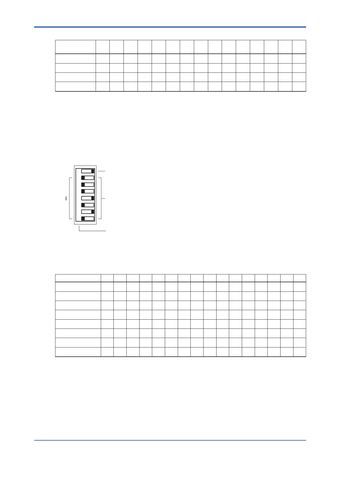
Setting the Station Number
Set the station number to a value from 1 to 64. T
o set a station number, set the DIP switches
as follows.
• Setting DIP switches
0: In the state shown in the following figure, the switch is tilted toward the left.
1: In the state shown in the following figure, the switch is tilted toward the right.
MSB : Most Significant Bit
LSB : Least Significant Bit
0
1
6
5
4
3
2
1
7 8
P
Station number
Station number parity (odd parity)
Bit number
MSB LSB
Figure 4.2.3-6 Station Number Setting Switches
Table 4.2.3-4 Station Number and DIP Switch Positions
Station number 1 2 3 4 5 6 7 8 9 10 11 12 13 14 15 16
Bit 1 0 0 1 0 1 1 0 0 1 1 0 1 0 0 1 0
Bit 2 0 0 0 0 0 0 0 0 0 0 0 0 0 0 0 0
Bit 3 0 0 0 0 0 0 0 0 0 0 0 0 0 0 0 0
Bit 4 0 0 0 0 0 0 0 0 0 0 0 0 0 0 0 1
Bit 5 0 0 0 0 0 0 0 1 1 1 1 1 1 1 1 0
Bit 6 0 0 0 1 1 1 1 0 0 0 0 1 1 1 1 0
Bit 7 0 1 1 0 0 1 1 0 0 1 1 0 0 1 1 0
Bit 8 1 0 1 0 1 0 1 0 1 0 1 0 1 0 1 0
<4.2 Processor Module > 4-11
IM 32Q06C10-31E 4th Edition : Jan.30,2015-00
 Loading...
