<Toc> <1. Installation>
1-5
IM 05D01D02-41E
1.3 How to Connect Wires
CAUTION
1) Before carrying out wiring, turn off the power to the controller and check that the
cables to be connected are not alive with a tester or the like because there is a possi-
bility of electric shock.
2) Wiring must be carried out by personnel who have basic electrical knowledge and
practical experience.
NOTE
1) Provide power from a single-phase instrument power supply. If there is a lot of noise in
the power line, insert an insulating transformer into the primary side of the line and use
a line filter (recommended part: ZAC2205-00U from TDK) on the secondary side.
As a countermeasures against noise, do not place the primary and secondary power
cables close to each other.
2) For thermocouple input, use shielded compensating lead wires for wiring. For RTD
input, use shielded wires that have low conductor resistance and cause no significant
differences in resistance between the three wires.
The cables to be used for wiring, terminal specifications, and recommended parts are
as shown below.
3) Control output relays may be replaced. However, because they have a life of 100,000
times that of the resistance load, use auxiliary relays to turn on/off a load.
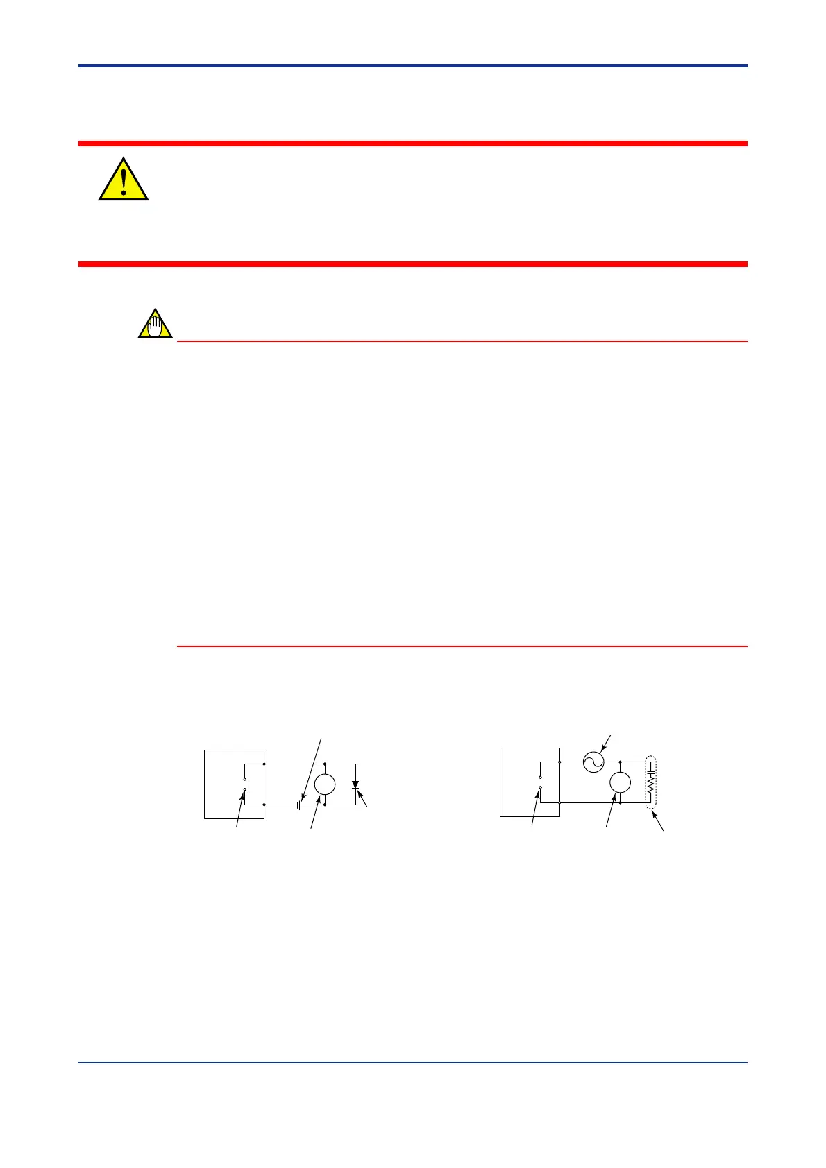
4) The use of inductance (L) loads such as auxiliary relays, motors and solenoid valves
causes malfunction or relay failure; always insert a CR filter for use with alternating
current or a diode for use with direct current, as a spark-removal surge suppression
circuit, into the line in parallel with the load.
■ For DC Relay Wiring ■ For AC Relay Wiring
UT350/UT320
UT’s contact
Diode
(Mount it directly
to the relay coil
terminal (socket).)
Relay
(Use one with a relay coil
rating less than the UT’s
contact rating.)
External DC power supply
R
R
UT350/UT320
CR filter
(Mount it directly
to the relay coil
terminal (socket).)
External AC power supply
Relay
(Use one with a relay coil
rating less than the UT’s
contact rating.)
UT’s contact
1st Edition : May 31,2000-00

 Loading...