5-4
<Toc> <5. Parameters>
IM 05D01D02-41E 1st Edition : May 31,2000-00
5.2 Lists of Parameters
* Parameters relating to PV or setpoints should all be set in real numbers.
For example, use temperature values to define target setpoints and alarm setpoints
for temperature input.
* The “User Setting” column in the table is provided for the customer to record setpoints.
* The column “Target Item in CD-ROM” in the table provides references from User’s
Manual (Reference) (CD-ROM version) which describes items in more detail and
items that are not contained in this manual.
* Numbers in ( ) are the parameter setpoints that apply when the communication func-
tion is used. ex. OFF (0), ON (1)
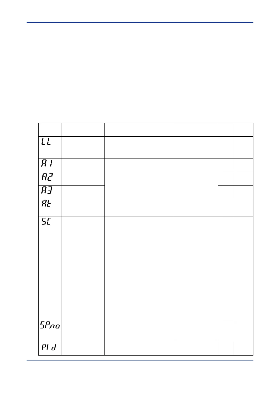
■ Operating Parameters
Parameter
Symbol
Name of Parameter Setting Range and Description Initial Value
User Setting
Target Item
in CD-ROM
Alarm 1-setpoint
Alarm 2-setpoint
Alarm 3-setpoint
PV alarm / SP alarm: -100.0 to 100.0% of PV
input range
Deviation alarm: -100.0 to 100.0% of PV input
range span
Output alarm: -5.0 to 105.0%
An alarm common to the 1.SP to 4.SP parameters.
PV high limit/SP high limit alarm:
100.0% of PV input range
Deviation alarm: 0.0% of PV
input range span
Other PV/SP low limit alarm:
0.0% of PV input range
Output high limit alarm: 100.0%
Output low limit alarm: 0.0%
Auto-tuning
OFF (0): No auto-tuning
1: Auto-tuning for 1.SP 2: Auto-tuning for 2.SP
3: Auto-tuning for 3.SP 4: Auto-tuning for 4.SP
AUTO (5): Performs auto-tuning to all groups 1 to 4.
OFF (0)
Target setpoint
number selection
0: Use target setpoint via communication.
1: Selects target setpoint 1 (1.SP).
2: Selects target setpoint 2 (2.SP).
3: Selects target setpoint 3 (3.SP).
4: Selects target setpoint 4 (4.SP).
1
PID parameter display
number
MENU (0): Move to FL parameter display
1Gr (1) to 4Gr (4): Display of each PID
parameter
MENU (0)
LL communication
interface selection
(A1)
(A2)
(A3)
(AT)
(SP.NO)
(PID)
OFF (0): Communication is carried out via the
RS485 communication terminals.
ON (1):
Communication is carried out via the light-
loader adapter. Note that the initial setting is “ON” if
the controller is equipped with a communication option.
OFF (0)
(LL)
OFF (0)
“Super” function
(SC)
ᎏ
ᎏ
ᎏ
ᎏ
ᎏ
Ref.2.1(5)
Ref.2.1(6)
Ref.4.1(1)
OFF (0): Disable
1: Overshoot suppressing function
Suppresses overshoots generated by abrupt
changes in the target setpoint or by
disturbances.
2: Hunting suppressing function (Stable mode)
Suitable to stabilize the state of control when
the load varies greatly, or the target setpoint is
changed.
Enables to answer the wider characteristic
changes compared with Response mode.
3: Hunting suppressing function (Response mode)
Enables quick follow-up and short converging
time of PV for the changed target setpoint.
Note: Use “SUPER” function (SC) 2 or 3 in PID
control or PI control.
“SUPER” function 2 or 3 is not available in the
following controls:
1) ON/OFF control
2) P control (control for proportional band only)
3) PD control (control for proportional band and
derivative item only)
4) Heating/cooling control
Do not use hunting suppressing function when
control processes with response such as flow or
pressure control.

 Loading...