2-2
<Toc> <2. Initial Settings>
IM 05D01D02-41E
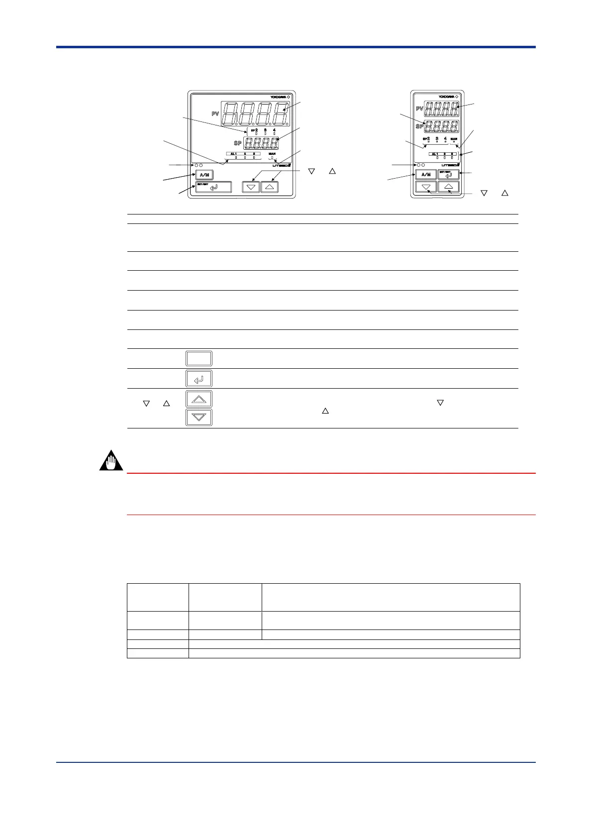
2.1 Names and Functions of Front Panel Parts
5. Alarm indicator
lamps
4. Status
indicator lamps
6. Light-loader
interface
7. A/M key
8. SET/ENT
key
1. Process
variable (PV)
display
2. Setpoint
display
1. Process
variable (PV)
display
2. Setpoint
display
5. Alarm
indicator
lamps
4. Status
indicator
lamps
6. Light-loader
interface
7. A/M key
8. SET/ENT key
3. Target setpoint
(SP) number
indicator lamps
3. Target setpoint
(SP) number
indicator lamps
9. and keys
9. and keys
Name of Part
Function
7.
A/M key
Used to switch between the AUTO and MAN modes. Each time you press the key, it switches to the
AUTO or MAN mode alternately.
8.
SET/ENT
key
SET/ENT
Used to switch or register a parameter. Pressing the key for more than 3 seconds allows you to switch
between the operating display and the menu for operating parameter setting display alternately.
9.
Used to change numerical values. On setting displays for various parameters, you can change target
setpoints, parameters, and output values (in manual operation). Pressing the key decreases a
numerical value, while pressing the key causes it to increase. You can hold down a key to gradually
increase the speed of change.
A/M
and
keys
1.
Process variable (PV)
display
Displays PV.
Displays a parameter symbol when you set a parameter.
Displays an error code (in red) if an error occurs.
2. Setpoint display
Displays the setpoint (SP) or the output value (OUT) during operation.
Displays the set value of parameters on the parameter setting display.
3.
Target setpoint (SP)
number indicator lamps
When the SP number currently used for operation is 2, 3 or 4, the respective SP No. indicator lamp lighits.
When the SP number is 1, the lamp does not lighit.
4.
Status indicator
lamp
Is lit in green during manual operation. MAN: Is lit when in manual mode.
Blinks during auto-tuning.
5. Alarm indicator lamps
If any of alarms 1 to 3 occurs, the respective alarm indicator lamp (AL1 to AL3) is lit (in orange).
6. Light-loader interface
Interface for an adapter cable used when setting and storing parameters from a PC.
This requires an optional parameter setting tool.
IMPORTANT
The controller automatically returns to the display at the time of power-on (i.e., operating
display) if no key is operated for at least one minute.
■ Setting of Main Parameters at the Factory before Shipment
Factory-set defaults
for standard type
controllers
Factory-set defaults
for heating/cooling type controllers
Control output
Control action Reverse action (variable) Not specified
PID parameter P = 5.0%, I = 240 seconds, D = 60 seconds.
Alarm output
Item
Alarm-1: PV high limit, Alarm-2: PV low limit, Alarm-3: PV high limit
Time proportional PID
relay output (variable)
Heating side: Time proportional PID relay output (variable)
Cooling side: Time proportional PID relay output (variable)
1st Edition : May 31,2000-00

 Loading...