2-6
<Toc> <2. Initial Settings>
IM 05D01D02-41E 1st Edition : May 31,2000-00
2.3 Changing PV Input Type
The following operating procedure describes an example of changing the K-type thermo-
couple (-199.9⬚C to 500.0⬚C) to a Pt100 resistance temerature detector (-199.9⬚C to
500.0⬚C) and setting the measurement range of 0.0⬚C to 200.0⬚C.
PV input terminal
Thermocouple/mV/V input
..............................
RTD input .................................................. --
131211
-
1312
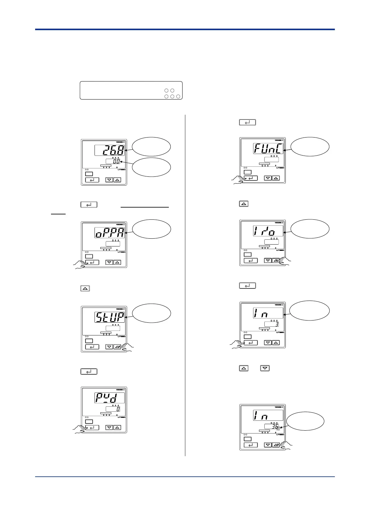
1.
Bring the operating display into view
(display appears at power on).
PV
MAN
A/M
SP
AL123
SP
234
SET/ENT
Displays
target setpoint.
Displays PV.
2.
Press the
SET/ENT
key for more than 3 sec-
onds to call up the menu “OP.PA”.
PV
MAN
A/M
SP
AL123
SP
234
SET/ENT
Displays
menu “OP.PA”.
3.
Press the key once to display the
menu “STUP”.
PV
MAN
A/M
SP
AL123
SP
234
SET/ENT
Displays
menu “STUP”.
4.
Press the
SET/ENT
key once to display the
parameter “PWD”.
PV
MAN
A/M
SP
AL123
SP
234
SET/ENT
5.
Press the
SET/ENT
key once to display the
menu “FUNC”.
PV
MAN
A/M
SP
AL123
SP
234
SET/ENT
Displays
menu “FUNC”.
6.
Press the key once to display the
menu “I/O”.
PV
MAN
A/M
SP
AL123
SP
234
SET/ENT
Displays
menu “I/O”.
7.
Press the
SET/ENT
key once to display the
parameter “IN” (PV input type).
PV
MAN
A/M
SP
AL123
SP
234
SET/ENT
Displays
parameter
“IN”.
8.
Press the or key to display the
required setpoint. The figure below is an
example of the controller set to a Pt 100
resistance temperature detector (-199.9⬚C
to 500.0⬚C).
PV
MAN
A/M
SP
AL123
SP
234
SET/ENT
Blinks during
change.

 Loading...