2-8
<Toc> <2. Initial Settings>
IM 05D01D02-41E 1st Edition : May 31,2000-00
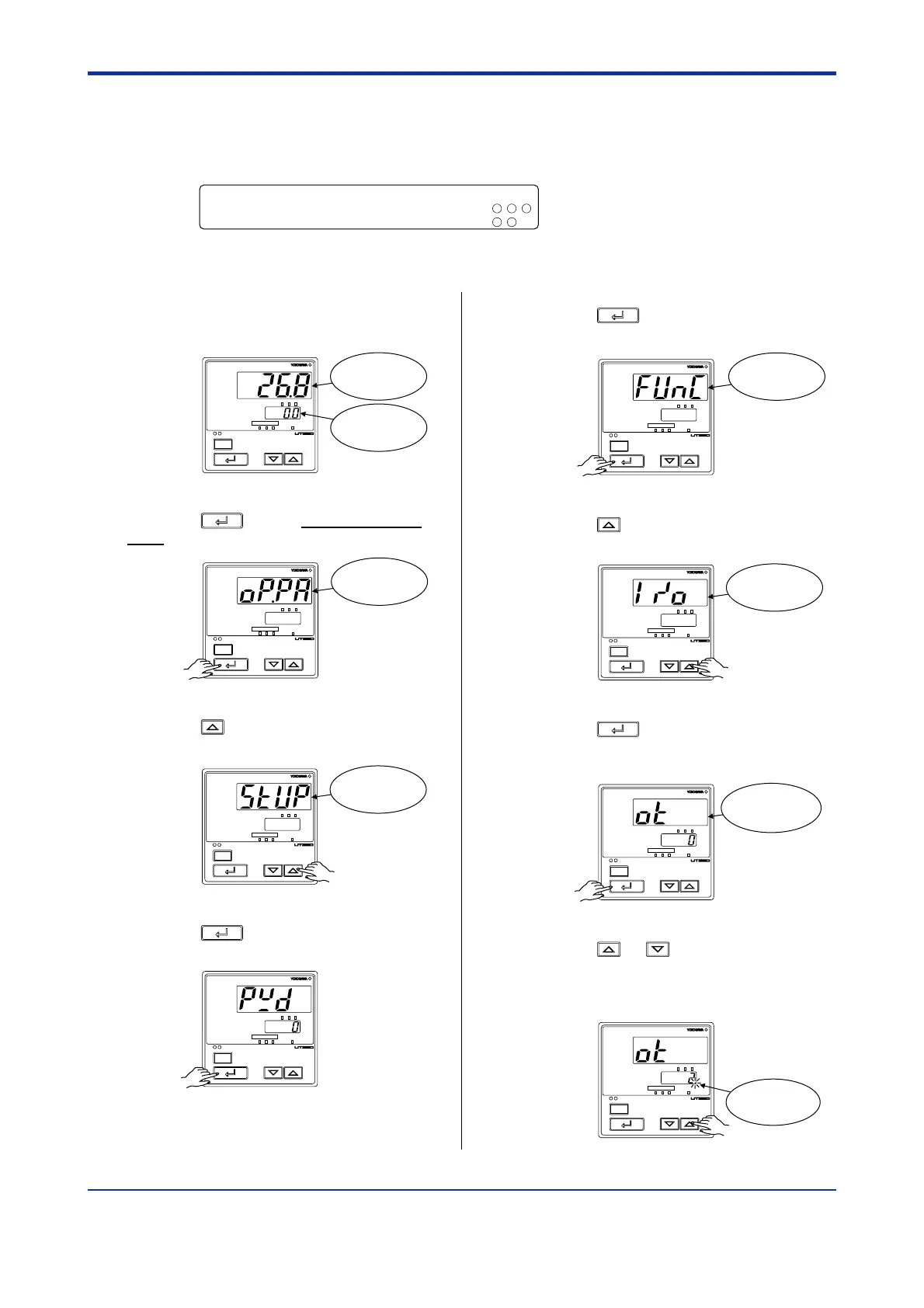
2.4 Setting Control Output Type
The following operating procedure describes an example of changing time proportional PID
relay output (0: factory-set default) to current output (2).
Control output terminal
Values in parentheses are setpoints
Time proportional PID relay (0)/on-off(3) output
...........................
Current (2)/time proportional PID voltage pulse (1) output
.............
--
1 2 3
-
16
17
For details on the heating/cooling control output terminals, see
“1.5 Terminal Wiring Diagrams.”
1.
Bring the operating display into view
(display appears at power on).
PV
MAN
A/M
SP
AL123
SP
234
SET/ENT
Displays
target setpoint.
Displays PV.
2.
Press the
SET/ENT
key for more than 3 sec-
onds to call up the menu “OP.PA”.
PV
MAN
A/M
SP
AL123
SP
234
SET/ENT
Displays
menu “OP.PA”.
3.
Press the key once to display the
menu “STUP”.
PV
MAN
A/M
SP
AL123
SP
234
SET/ENT
Displays
menu “STUP”.
4.
Press the
SET/ENT
key once to display the
parameter “PWD”.
PV
MAN
A/M
SP
AL123
SP
234
SET/ENT
5.
Press the
SET/ENT
key once to display the
menu “FUNC”.
PV
MAN
A/M
SP
AL123
SP
234
SET/ENT
Displays
menu “FUNC”.
6.
Press the key once to display the
menu “I/O”.
PV
MAN
A/M
SP
AL123
SP
234
SET/ENT
Displays
menu “I/O”.
7.
Press the
SET/ENT
key several times to
display the parameter “OT” (control output
type).
PV
MAN
A/M
SP
AL123
SP
234
SET/ENT
Displays
parameter
“OT”.
8.
Press the or key to display the
required setpoint. The figure below shows
an example of setting to current output (4
to 20 mA DC).
PV
MAN
A/M
SP
AL123
SP
234
SET/ENT
Blinks during
change.

 Loading...