1
2
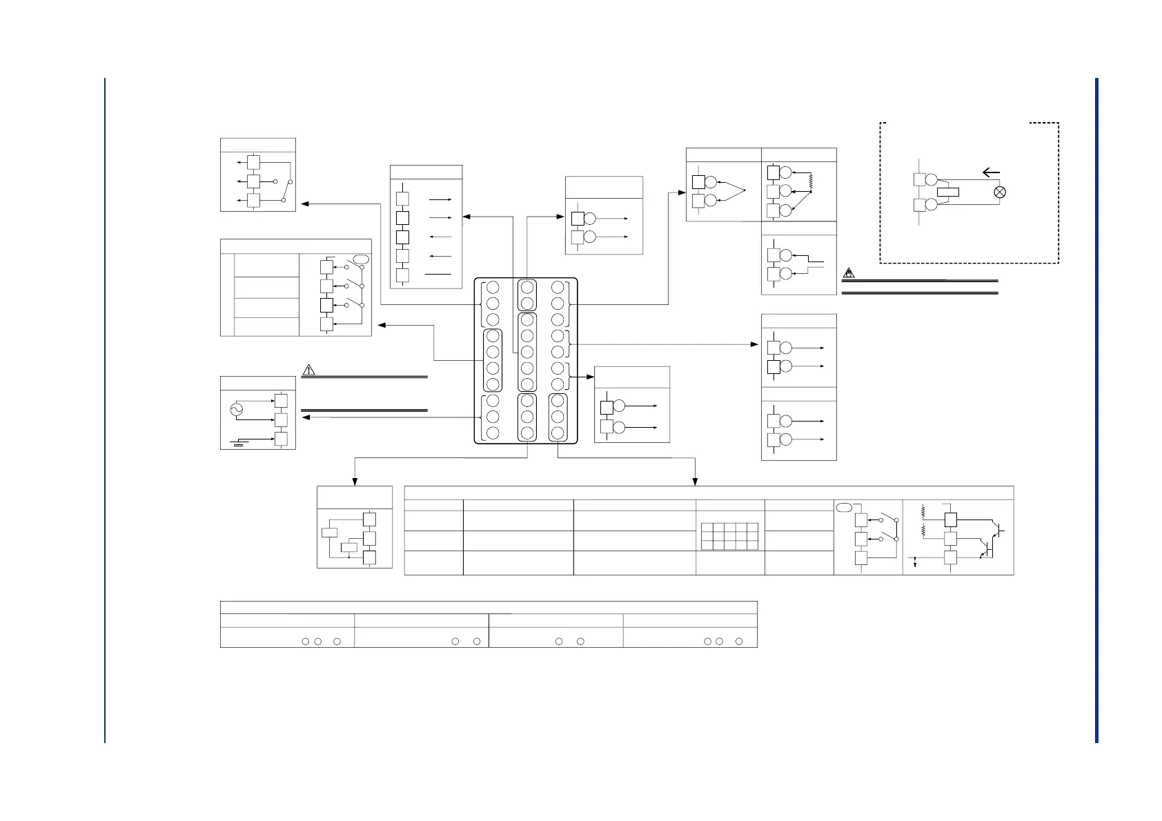
Relay contact output
3
Control output
NC
NO
COM
Contact rating: 250 V AC, 3 A
30 V DC, 3 A (resistance load)
Note: Select this option from
the OT parameter.
* Time proportional PID
relay contact output is
configured at factory
before shipment.
23
24
RS-485 communication
* Wiring can only be carried out
for controllers with
communication functions.
Maximum baud rate: 9600 bps
25
26
27
SDB(+)
SDA(-)
RDB(+)
RDA(-)
SG
* Wiring can only be carried
out for controllers with
24 V DC loop power supply.
8
9
Power supply
10
L
N
Allowable range: 100 to 240 V AC (
10%)
(free voltage)
50/60 Hz shared
Power supply
CAUTION
Before carrying out wiring, turn off the power
to the controller and check that cables to be
connected are not alive with a tester or the like
because there is a possibility of electric shock.
6
5
Alarm output
4
7
AL1
AL2
AL3
COM
Relay contact rating: 240 V AC, 1 A
30 V DC, 1 A (resistance load)
Relay
Alarm-1 output
Alarm-2 output
Alarm-3 output
Common
UT
16
17
Current/voltage
pulse output
4-20 mA DC,
voltage pulse
(12 V)
Control output
+
-
Note:Select this option
from the OT
parameter.
12
13
TC input
11
12
RTD input
13
12
13
mV/V input
Installation category (overvoltage category): II (IEC1010-1)
A
b
B
NOTE
-
+
-
+
12
13
Note: Connecting a 250
Ω resistor to the terminals is
optional.
Model: X010-250-2 (resistor with M3.5 crimp-on terminal
lugs)
*
When receiving 4-20 mA DC current signals,
set the PV input type to 1-5 V DC (setpoint
“41”).
䊏
Receiving 4-20 mA DC Current
Signals with the Controller
250 Ω
4-20mA
PV input
* Not configured at factory before shipment
See “2. Initial Settings,
” for more
information.
-
+
14
15
Retransmission output
4-20 mA DC
14
15
15 V DC loop power supply
14.5-18.0VDC
(21 mA DC max.)
* PV retransmission is configured at factory
before shipment.
Load resistance: 600
Ω or less
* If 15 V DC loop power supply is used,
retransmission output cannot be used.
-
+
-
+
* This wiring is only
possible for a controller
with a heater burnout
alarm.
29
28
Heater current
detection input
30
CT2
CT1
COM
CT
CT
OT=0 (factory-set default)
Time proportional control
Relay output (terminals , and )
OT=1
Correspondence between parameter OT and control output types
Time proportional control
Voltage pulse output (terminals and )
OT=2
Current output
(terminals and )
OT=3
On-off control
Relay output (terminals , and )
* OT is a setup parameter. You can change the settings of the parameter OT to change the control output type.
See “2. Initial Settings,
” for more information.
1
2
3
16
17
16
17
1
2
3
When switching target
setpoints 1 to 4:
DI1
DI2
1.SP
2.SP3.SP
4.SP
OFF
OFFOFF
ON ON
ON
OFF
ON
Contact rating: 12 V DC, 10 mA or more
Correspondence between parameter DIS and external contact input functions
When DIS=4
DI1
DI2
COM
Common
When DIS=3
2.SP when DI1=ON
1.SP when DI1=OFF
STOP when DI2=ON
RUN when DI2=OFF
Common
When DIS=2
Hides the LOCK parameter when DI1=ON.
Shows the LOCK parameter when DI1=OFF.
Common
When DIS=1 (Factory-set default)
2.SP when DI1=ON
1.SP when DI1=OFF
AUTO when DI2=ON
MAN when DI2=OFF
Common
When DIS=OFF
No function
No function
Common
DI1
DI2
COM
+5V
+5V
Contact
Transistor contact
*
DIS is a setup parameter.
Changing DIS setpoint allows you to change the function of external contact input.
No function
19
18
20
UT
19
18
20
1
2
3
4
5
6
7
8
9
10
21
22
23
24
25
26
27
28
29
30
11
12
13
14
15
16
17
18
19
20
24 V DC loop
power supply
21
22
21.6-28.0VDC
(30 mA DC max.)
-
+
Note: External Contact Input
If the power is turned on when the external contact input is OFF, the
mode (SP.no or A/M) existing before the power is turned off will be
continued. (except for RUN/STOP)

 Loading...