<Toc> <6. Function Block Diagram and Descriptions>
6-5
IM 05D01B02-41E 1st Edition : May 31,2000-00
Functions and Parameters for “Single-loop Control” in Initial State (Fac-
tory-set default)
Functions and parameters in initial state are given in the tables below. For details on each
parameter, refer to “5.2 Lists of Parameters.”
■ PV Input
PV input (INPUT1) is a universal input, which can receive signals from thermocouple, RTD,
or DC voltage signals. The controller is capable of biasing, square root extraction, first-
order lag computation (filtering) ten-segment linearizer approximation, and ten-segment
linearizer biasing on input signals.
Each function can be set by the following parameters.
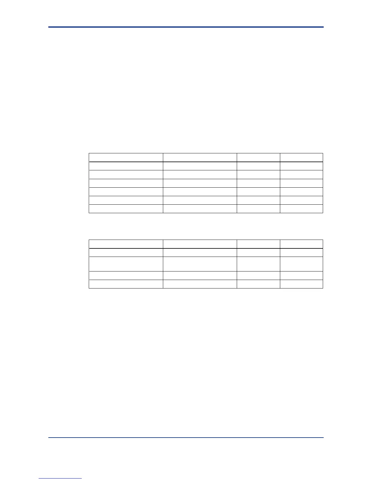
Setup Parameters
Function Parameter
Input selection IN1
Unit selection UNI1
Analog input range conversion RH1, RL1 (SDP1, SH1, SL1)
UTMD
UTMD
UTMD
IN
IN
IN
Analog input bias A.BS1
Square root extraction A.SR1, A.LC1
Analog input filter A.FL1
CMLP
CMLP
CMLP
AIN
AIN
AIN
Main menu Submenu
Operating Parameters
Function Parameter
Ten-segment linearizer mode 1.PMD
Ten-segment linearizer
approximation/biasing
1.a1 to 1.a11, 1.b1 to 1.b11
PV input bias BS
PYS1
PYS1
LP1
None
None
PAR
PV input filter FL LP1 PAR
Main menu Submenu
Note: PV input bias (BS) and PV input filter (FL) among the operating parameters are used as bias and filter when normal
operation. Analog input bias (A.BS1) and analog input filter (A.FL1) among the setup parameters are used when PV
correction value is decided in advance.

 Loading...


