2-16
<Toc> <2. Initial Settings>
IM 05D01B02-41E
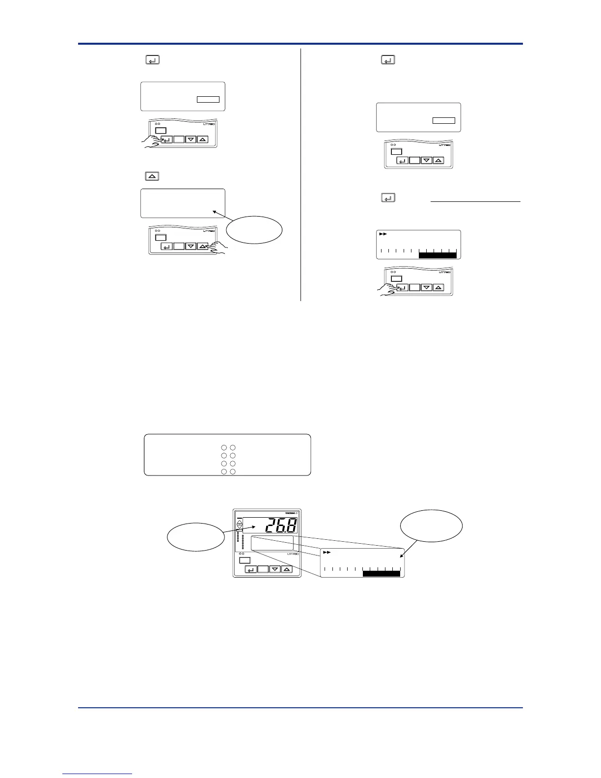
8.
Press the
SET/ENT
key once to display the
parameter “INI”.
SETUP
A/M
DISP
SET/ENT
MENU:UTMD/INIT #1
parameter initialize
INI = OFF
9.
Press the key to display “ON”.
MENU:UTMD/INIT #1
changing
parameter initialize
INI = ON
A/M
DISP
SET/ENT
Blinks during
change.
10.
Press the
SET/ENT
key once. The display
momentarily becomes blank (which is
normal), indicating the parameters have
been initialized.
SETUP
A/M
DISP
SET/ENT
MENU:UTMD/INIT #1
parameter initialize
INI = ON
11.
Press the
SET/ENT
key for more than 3 seconds.
This returns you to the display shown at
power-on (figure below).
A/M
DISP
SET/ENT
SP :
1.
-10 0 +10
0.0°C
DV
2.7 Changing Alarm Type
The following operating procedure describes an example of changing alarm 1 (factory-set
to the PV high limit alarm) to the PV low limit alarm.
When you have changed alarm type, the alarm setpoint will be initialized; set the alarm
setpoint again.
-
7
6
-
7
5
-
7
4
-
3534
Alarm output terminals Factory-set defaults
Alarm-1(terminal numbers )..........PV high limit alarm
Alarm-2(terminal numbers )..........PV low limit alarm
Alarm-3(terminal numbers )..........PV high limit alarm
Alarm-4(terminal numbers )..........PV low limit alarm
1.
Bring the operating display into view (display appears at power-on).
AL
A/M
PV
REM1
CAS
REM2
MAN1
MAN2
STP
2
4
1
3
PV2
AL
DISP
SET/ENT
SP :1.
-10 0 +10
0.0°C
DV
Displays
target setpoint-1
“1.SP”.
Displays PV.
In steps 2 and later, illustrations of the LCD are cited to explain the procedure.
1st Edition : May 31,2000-00

 Loading...


