3-8
<Toc> <3. Operations>
IM 05D01B02-41E
8.
Press the
SET/ENT
key once to register the
setpoint.
A/M
DISP
SET/ENT
MENU:LP1/1.PID #6
proportional band
1.P = 18.0%
The same steps can be used for integral
time (1.I) and derivative time (1.D) that are
displayed after this.
1st Edition : May 31,2000-00
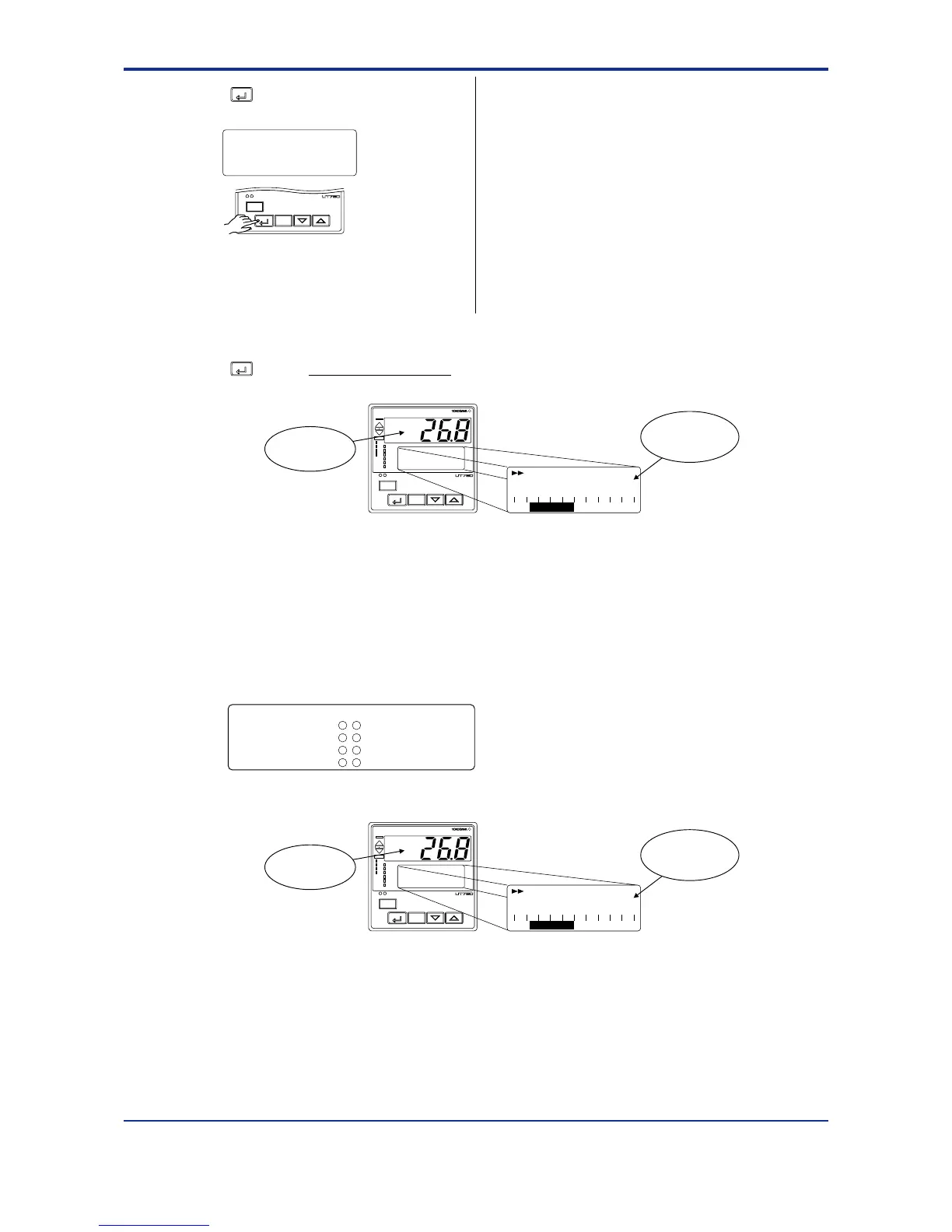
9.
Press the
SET/ENT
key for more than 3 seconds. This returns you to the display shown at power-on
(figure below).
AL
A/M
PV
REM1
CAS
REM2
MAN1
MAN2
STP
2
4
1
3
PV2
AL
DISP
SET/ENT
SP :1.
-10 0 +10
100.0°C
DV
Displays PV.
Displays
target setpoint-1
“1.SP”.
3.5 Setting Alarm Setpoints
The following operating procedure describes an example of setting 160.0 to alarm-1
setpoint. Check alarm type before setting the alarm setpoint.
When changing the alarm type, see “2.7 Changing Alarm Type.”
Alarm output terminals Factory-Set defaults
Alarm-1 (terminal numbers )............PV high limit alarm
Alarm-2 (terminal numbers )............PV low limit alarm
Alarm-3 (terminal numbers )............PV high limit alarm
Alarm-4 (terminal numbers )............PV low limit alarm
-
7
-
5 7
-
4 7
-
34
35
6
1.
Bring the operating display into view (display appears at power on)
AL
A/M
PV
REM1
CAS
REM2
MAN1
MAN2
STP
2
4
1
3
PV2
AL
DISP
SET/ENT
SP :1.
-10 0 +10
100.0°C
DV
Displays PV.
Displays
target setpoint-1
“1.SP”.
In steps 2 and later, illustrations of the LCD are cited to explain the procedure.
[TIP]
For the PID parameter number you set in
step 5, select:
the submenu “1.PID” if the PID con-
stants are for 1.SP;
the submenu “2.PID” if the PID con-
stants are for 2.SP;
the submenu “3.PID” if the PID con-
stants are for 3.SP; and
the submenu “4.PID” if the PID con-
stants are for 4.SP.

 Loading...


