<Toc> <1. Installation>
1-9
IM 05D01B02-41E 1st Edition : May 31,2000-00
• Relay contact output
(Single-loop type: terminals
1
-
2
-
3
, heating-side output: terminals
1
-
2
-
3
, cool-
ing-side output: terminals
4
-
7
, position proportional type: terminals
48
-
49
-
50
)
Number of outputs
1 or 2 (two for heating/cooling control)
Output signal Three terminals (NC, NO, and common)
Contact rating 250 V AC or 30 V DC, 3 A (resistance load)
Resolution 10 ms or 0.1% of output, whichever is larger
Contact Inputs
• Purpose: Target setpoint selection, remote/local mode switching, and run/stop switch-
ing
• Number of inputs: 7
• Input type: Non-voltage contact or transistor open collector input
• Input contact rating: 12 V DC, 10 mA or more
• On/off determination: For non-voltage contact input, contact resistance of 1 k or less
is determined as “on” and contact resistance of 20 k or more as “off.”
For transistor open collector input, input voltage of 2 V or less is determined as “on”
and leakage current must not exceed 100 A when “off.”
• Minimum status detection hold time: PV input’s sampling period 3
Contact Outputs
• Purpose: Alarm output, FAIL output, and others
• Number of outputs: 7 (relay: 3, transistor: 4)
• Relay contact rating: 240 V AC, 1 A, or 30 V DC, 1 A (COM terminal is common)
• Transistor contact rating: 24 V DC, 50 mA (COM terminal is common)
Display Specifications
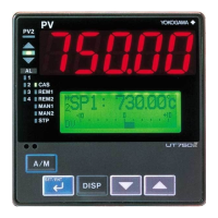
• PV display: 5-digit, 7-segment, red LEDs, character height of 20 mm for UT750
• Setpoint display: 32128 dot LCD display with back-light
• Status indicating lamps: LEDs
Safety and EMC Standards
• Safety: Compliant with IEC1010-1: 1990 and EN61010-1: 1992
Approved by CSA1010
CSA1010 installation category (overvoltage category): CATII (IEC1010-1)
Approved by UL508
• EMC standards: This instrument complies with the following EMC standards (the
instrument continues to operate at a measuring accuracy of within 20% of the range
during tests):
- EMI (emission), EN55011: Class A Group 1
- EMS (immunity), EN50082-2: 1995

 Loading...