2-4
<Toc> <2. Initial Settings>
IM 05D01B02-41E
The following operating procedure describes an example of setting a K-type thermocouple
(-200.0 to 500.0⬚C) and a measurement range of 0.0 to 200.0⬚C.
1.
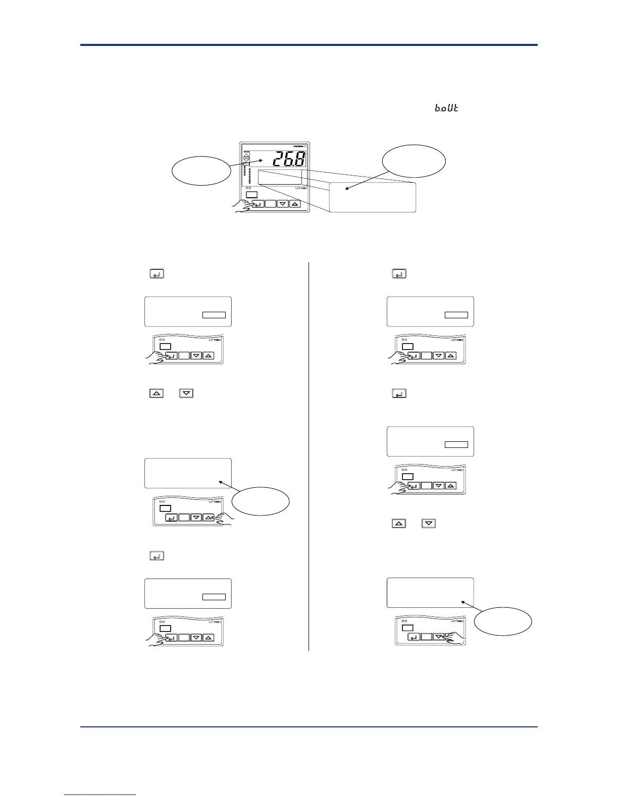
Display view at power-on
The PV display in the figure below shows the error code for input burnout ( ) if PV input
wiring is not yet complete. The error code disappears when you wire the PV input terminals cor-
rectly.
AL
A/M
PV
REM1
CAS
REM2
MAN1
MAN2
STP
2
4
1
3
PV2
AL
DISP
SET/ENT
input set
SETUP sub menu
IN
Displays
submenu
“IN”.
Displays PV.
In steps 2 and later, illustrations of the LCD are cited to explain the procedure.
1st Edition : May 31,2000-00
2.
Press the
SET/ENT
key once to display the
parameter IN1 (PV input type).
MENU:UTMD/IN #1
SETUP
input 1 type select
IN1 = OFF
A/M
DISP
SET/ENT
3.
Press the or key to display the
required setpoint.
The figure below shows an example of
setting a K-type thermocouple (-200.0⬚Cto
500.0⬚C). See “Instrument Input Range
Codes.”
MENU:UTMD/IN #1
changing
input 1 type select
IN1 = typeK3
A/M
DISP
SET/ENT
Blinks during
change.
4.
Press the
SET/ENT
key once to register the
setpoint.
A/M
DISP
SET/ENT
MENU:UTMD/IN #1
input 1 type select
IN1 = typeK3
SETUP
5.
Press the
SET/ENT
key once to display the
parameter “UNI1” (PV input unit).
SETUP
A/M
DISP
SET/ENT
MENU:UTMD/IN #2
input 1 unit select
UNI1 = °C
6.
Press the
SET/ENT
key once to display the
parameter “RH1” (maximum value of PV
input range).
SETUP
A/M
DISP
SET/ENT
MENU:UTMD/IN #3
input 1 range high
RH1 = 500.0
7.
Press the or key to display the
required setpoint.
The figure below shows an example of
setting the maximum value of the PV input
range to 200.0⬚C.
MENU:UTMD/IN #3
changing
input 1 range high
RH1 = 200.0
A/M
DISP
SET/ENT
Blinks during
change.

 Loading...


