4-10
<Toc> <4. Troubleshooting and Maintenance>
IM 05D01B02-41E 1st Edition : May 31,2000-00
6.
Pull out the relay to be replaced.
The control output relays are easy to remove and mount, since they are connected via a
socket onto the print boards.
Insert the new relay in the socket. Use the following relay.
Manufacturer OMRON
Model G6B-2114P-FD-US-P6B
Power supply 12 V DC
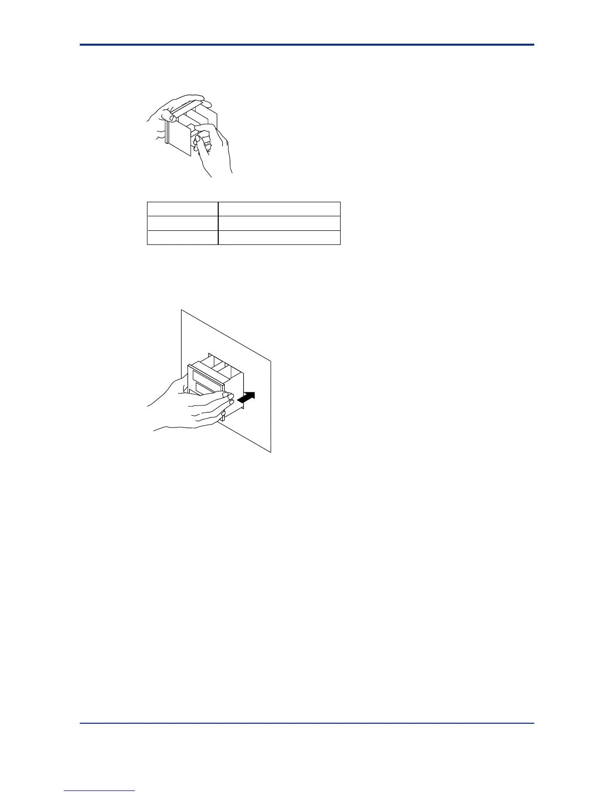
7.
Insert the internal unit into the housing.
Apply power to the controller and confirm that the initial operating display is shown.
If the operating display is not shown properly, turn off the controller and pull out the
internal unit. Then, insert it into the housing again.
This completes replacement of the control output relay.

 Loading...


