5-4
<Toc> <5. Parameters>
IM 05D01B02-41E
AL4
AL3
AL2
AL1
HY3
HY2
HY1
DY1
HY4
DY3
DY2
DY4
AMD
ALM CTL
SET
ZON
AR
MOD
OPR
GRP
R.TM
R.MD
2.RP
1.RP
4.RP
3.RP
5.RP
RHY
6.RP
RDV
SET
TMU
PVT
SPT
RMS
SPL
SPH
SET
SP
RET2
RTL1
RTH1
RET1
RTL2
RTH2
RET LOCK
SET
LP1
MODE
A/M
USR
PID
LP2
PYS2
PYS1
PWD
SET
A.LC1
A.SR1
A.FL1
A.BS1
A.LC2
A.SR2
SET
AIN
LOOP2
A.FL2
A.BS2
A.LC3
A.SR3
A.FL3
A.BS3
TRND
DVB2
DVB1
TSC2
TSC1
TTM
SET
*1
*2
*3
Main menu
submenu
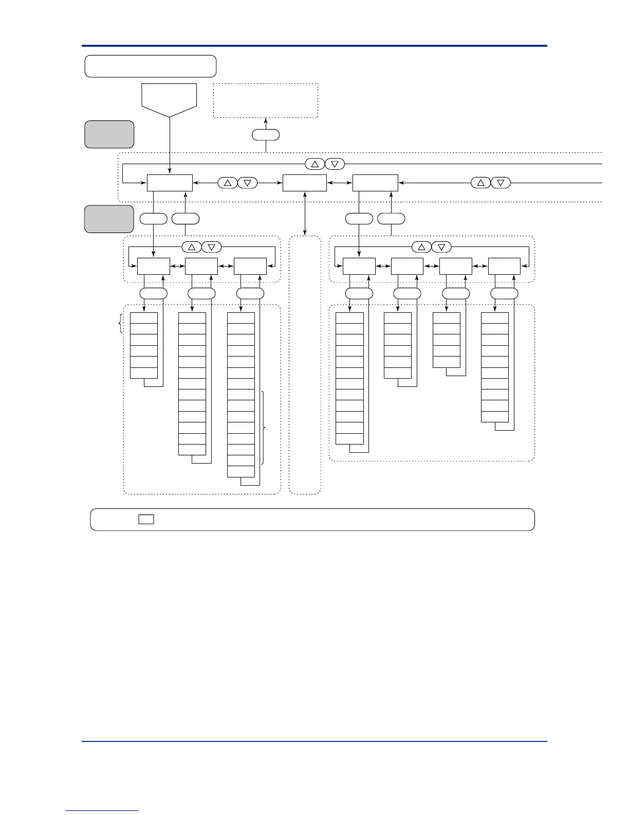
UT750 Setup Parameter Map
DISP
Pressing the key once when a parameter setting display is shown retrieves the submenu of that parameter setting display.
Same
as
LOOP1
However,
RMS
ZON
R.MD
R.TM
are not
contained.
*1 Parameters RMS and SPT are displayed only for the controller with auxiliary analog (remote) input.
*2 Displayed when parameter ZON is “1.”
*3 Main menu LOOP2 is displayed when UT mode is “Cascade control,” “Dual-loop control,” “Temperature and humidity
control,” or “Cascade control with two universal inputs.”
䉲/䉱
DISP
OK
DISP
To operating parameter setting
display main menu [MODE]
(on the previous page)
Password
check display
SET
DISP
LOOP1
CMLP
SET
DISP
1st Edition : May 31,2000-00

 Loading...


