<Toc> <5. Parameters>
5-21
IM 05D01B02-41E
● Output-related Parameters
Located in: Main menu = UTMD ; Submenu = OUT
Ref.3.3(4)
Ref.2.1(7)
Parameter
Symbol
Name of Parameter Setting Range and Description Initial
Value
User
Setting
Target Item
in CD-ROM
1 2 3
1 2 3
1 2 3
1 2 3
16 17
16 17
16 17
16 17
16 17
4 7
4 7
4 7
34 35
1 2 3
14 15
34 35
16 17
34 35
16 17
14 15
16 17
14 15
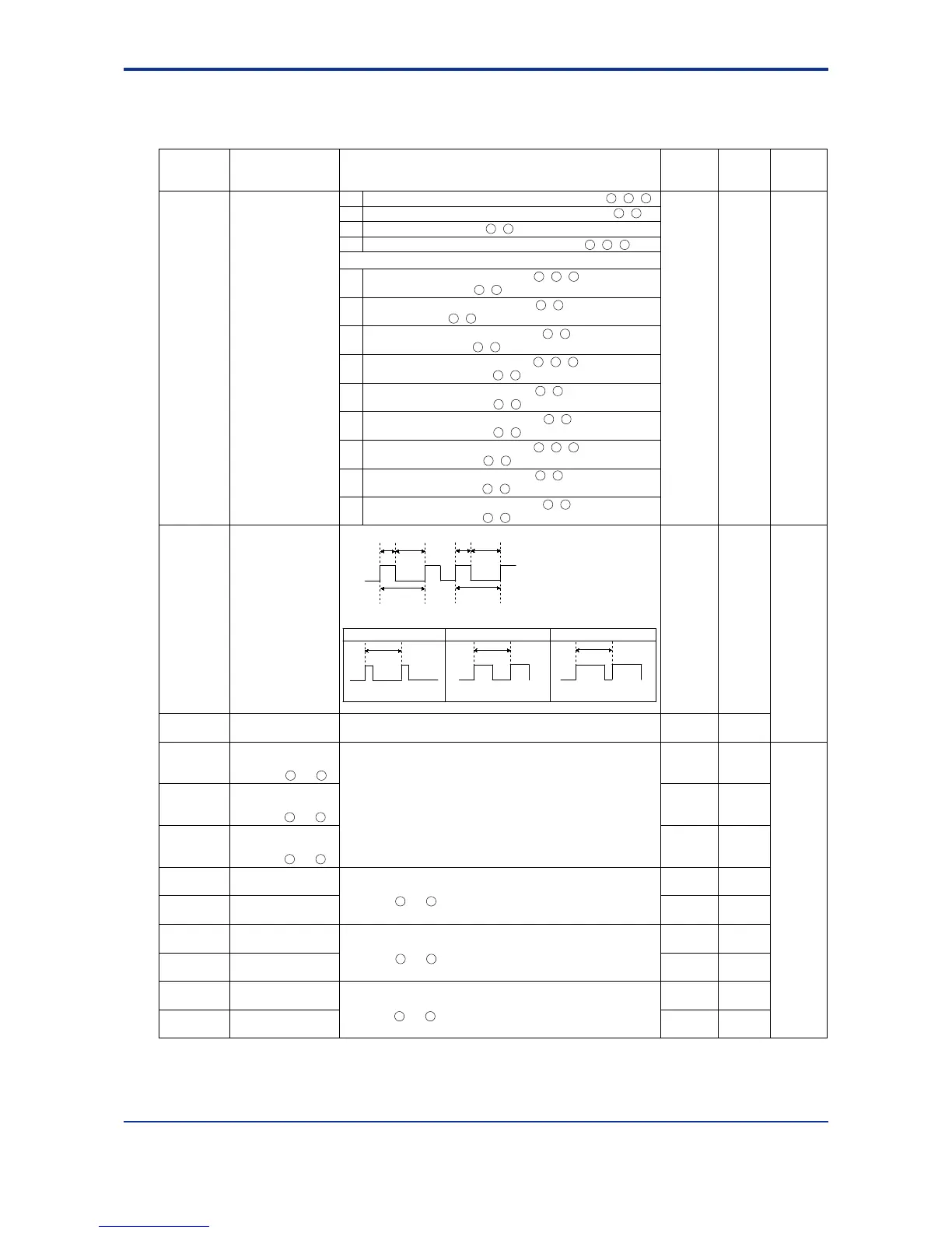
Relay’s Behavior when Cycle Time = 10 sec.
10 sec.
On-state duration: 5 sec.
Off-state duration: 5 sec.
On-state duration: 8 sec.
Off-state duration: 2 sec.
On
Off
On
Off
Cycle time Cycle time
For 20% of Control Output For 50% of Control Output For 80% of Control Output
Off-state duration: 8 sec.
On-state duration: 2 sec.
10 sec.10 sec.
16 17
16 17
14 15
14 15
46 47
46 47
Control output
type
0
Control output cycle
time
Heating-side control
output cycle time
(in heating/cooling
control)
Cooling-side control
output cycle time
1 to 1000 sec. 30 sec.
1 to 1000 sec. 30 sec.
OT1
CT1
CTc1
AO1
AO2
AO3
A1H
A1L
A2H
A2L
A3H
A3L
Time proportional PID relay contact output (terminals - - )
Time proportional PID voltage pulse output (terminals - )
Current output (terminals - )
ON/OFF control relay contact output (terminals - - )
0
1
2
3
4
5
6
7
8
9
10
11
12
Analog output-1 type
(OUTPUT 1:
Terminals and )
Analog output-3 type
(OUTPUT 3:
Terminals and )
0
0
Allows control output or retransmission output to be presented
as one of the following current signals.
0: 4 to 20 mA
1: 0 to 20 mA
2: 20 to 4 mA
3: 20 to 0 mA
0
Analog output-1 100%
segmental
point
Analog output-2 100%
segmental point
Analog output-2 0%
segmental
point
Analog output-3 100%
segmental
point
Analog output-3 0%
segmental
point
Analog output-1 0%
segmental
point
100.0%Set the values of segmental points for the 0% and 100% output
levels at which the values are presented via OUTPUT-1
(terminals and ). See “■ Performing Split Computations” below.
-5.0% to 105.0%
Set the values of segmental points for the 0% and 100% output
levels at which the values are presented via OUTPUT-3
(terminals and ). See “■ Performing Split Computations” below.
-5.0% to 105.0%
0.0%
100.0%
0.0%
100.0%
0.0%
Set the values of segmental points for the 0% and 100% output
levels at which the values are presented via OUTPUT-2
(terminals and ). See “■ Performing Split Computations” below.
-5.0% to 105.0%
Analog output-2 type
(OUTPUT 2:
Terminals and )
Heating-side relay output (terminals - - ), cooling-side
relay output (terminals - )
Heating-side pulse output (terminals - ), cooling-side relay
output (terminals - )
Heating-side current output (terminals - ), cooling-side
relay output (terminals - )
Heating-side relay output (terminals - - ), cooling-side
transistor output (terminals - )
Heating-side pulse output (terminals - ), cooling-side
transistor output (terminals - )
Heating-side current output (terminals - ), cooling-side
transistor output (terminals - )
Heating-side relay output (terminals - - ), cooling-side
current output (terminals - )
Heating-side pulse output (terminals - ), cooling-side
current output (terminals - )
Heating-side current output (terminals - ), cooling-side
current output (terminals - )
1st Edition : May 31,2000-00

 Loading...


