6-2
<Toc> <6. Function Block Diagram and Descriptions>
IM 05D01B02-41E 1st Edition : May 31,2000-00
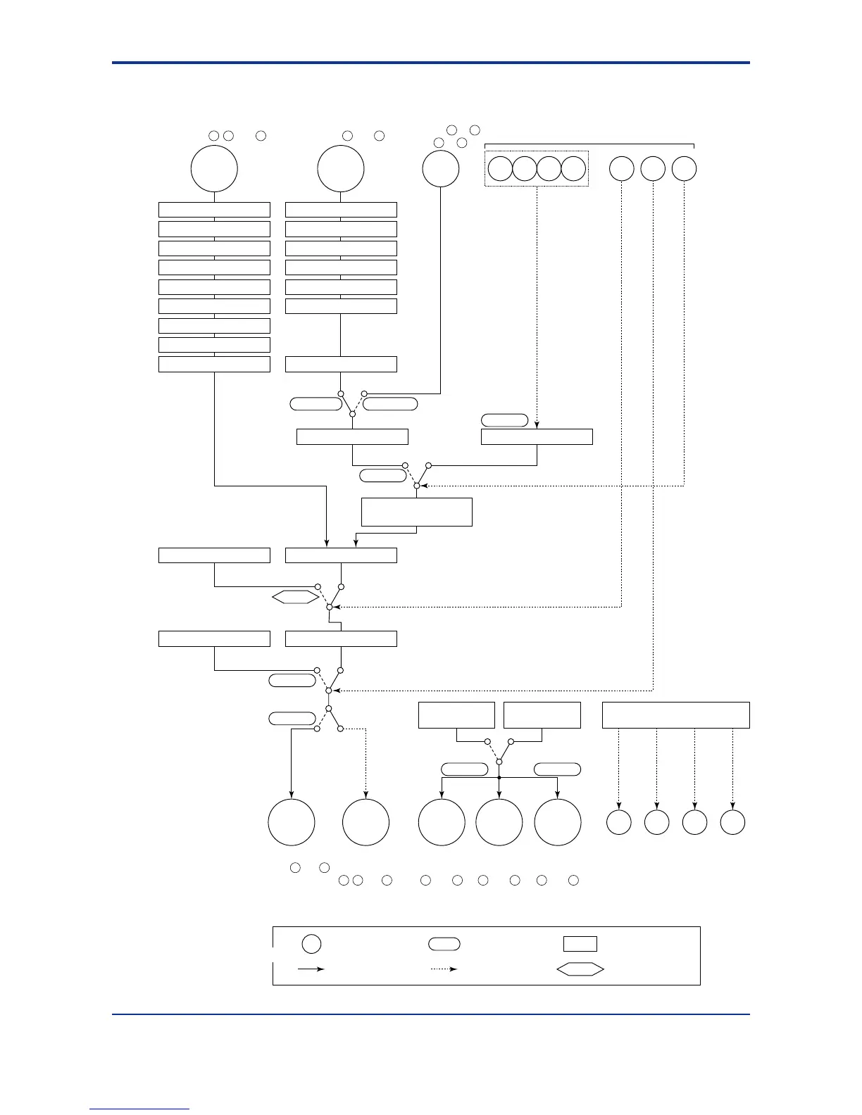
■ Function Block Diagram for Single-loop Control
RMS=COMRMS=RSP
SPNO
R/L
RS485
OT1
S/R
A/M
OUTPUT1 OUTPUT1 OUTPUT1 OUTPUT3
RET2 RET1
OUTPUT2 DO4DO3DO2DO1
DI1 DI2 DI3 DI4 DI5 DI6 DI7INPUT1 INPUT3
Communication
terminals to
and to
PV input
terminals , and
Remote input
terminals and
12 1311
2221
2723
3028
Input selection
Unit selection
Analog input range conversion
Analog input bias
Square root extraction
Analog input filter
Analog input range conversion
Analog input bias
Square root extraction
Analog input filter
10-seg. linearizer approx./bias
PV input bias
PV input filter
Input selection
Unit selection
Contact input
Target setpoint selection
Target setpoints 1 to 8
REMOTE (ON)/LOCAL (OFF) switching
Communication
Aux.Input
LOCALREMOTE
Remote setting filter
Ratio/bias calculation
Control computationManual operation
Preset output
AUTO (ON)/MAN (OFF) switching
AUTOMAN
Target setpoint
ramp-rate function
Output limiter
STOP (ON)/RUN (OFF) switching
RUNSTOP
15 V loop
power supply
Retransmission
output
Alarm function
Alarm 1 Alarm 2 Alarm 3 Alarm 4
Control
output
1716
Current or pulse
terminals and
Relay
terminals
, and
2 31
Current
terminals
and
1514
Current
*1
terminals
and
1716
Current
*2
terminals
and
4746
*1: Unavailable when control output is current or pulse.
*2: Unavailable for dual-loop controller.
Terminal Parameter Function
Analog signal Contact signal Front panel key
Legend

 Loading...


