YORK INTERNATIONAL
26
FORM 160.73-N1 (904)
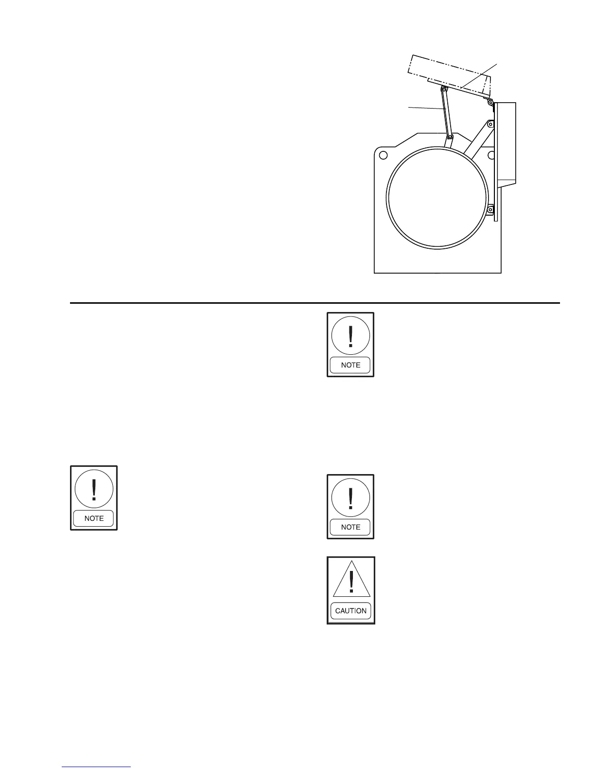
CONTROL PANEL POSITIONING (See Fig. 15)
On units with evaporator codes G thru X, the
OptiView™ Con trol Center is placed in a position above
the evaporator for shipping. To move the con trol center
into position for operation, pro ceed as follows:
1. While supporting the control center, remove
the hardware between the support arms and the
evap o ra tor.
2. Swing the control center into a vertical position.
3. Slide the control center down the guide rails to the
proper position. Tighten securely.
4. Discard unused hardware.
CONTROL WIRING
On units shipped disassembled, after in stal la tion of
the con trol center, control wiring must be completed
be tween unit com po nents and control center, solid state
starter, or vari able speed drive, when used, using wir ing
har ness fur nished. Refer to Form 160.73-N3.
Field wiring connections for commonly encountered
con trol modifi cations (by others) if required, are shown
on Form 160.73-PW4.
No deviations in unit wiring from that
shown on draw ings furnished shall be
made with out pri or ap prov al of the
YORK representative.
POWER WIRING
Chiller with Electro-Mechanical Starter
A 115 volt – single phase – 60 or 50 Hertz power sup ply
of 20 amperes must be fur nished to the control cen ter,
from the con trol trans form er (2 KVA required) in clud ed
with the com pres sor motor starter. DO NOT make fi nal
power con nec tions to con trol center until approved by
YORK rep re sen ta tive.
OIL PUMP – 3 PHASE STARTER
Separate wiring or a fused disconnect switch should be
sup plied by the installer.
SUPPORT
ARMS
PANEL
TRACK
FIG. 15 – CONTROL PANEL POSITIONING
Remote Electro-Mechanical starters
for the chill er must be furnished in ac-
cor dance with YORK Starter Specifi ca-
tions Product Draw ing Form 160.73-
PA1 to pro vide the fea tures nec es sary
for the start er to func tion prop er ly with
the YORK con trol system.
Each chiller unit is furnished for a specifi c electrical
pow er supply as stamped on the Unit Data Plate, which
also details the motor connection di a grams.
To in sure proper motor ro ta tion the
start er pow er in put and starter to mo-
tor con nec tions must be checked with
a phase se quence in di ca tor in the pres-
ence of the YORK rep re sen ta tive.
DO NOT cut wires to final length
or make fi nal con nec tions to motor
ter mi nals or start er power input ter-
mi nals until ap proved by the YORK
rep re sen ta tive.
YK Motors (Electro-Mechanical Starter)
Fig. 16 shows the power wiring hook-up for Motor
Con nec tions. (Refer to Wiring Labels in Motor Ter mi nal
Box for hook-up to suit motor voltage and am per age.)
Motor leads are furnished with a crimp type con nec tion
LD03826

 Loading...