YORK INTERNATIONAL
4
FORM 160.73-N1 (904)
TABLE OF CONTENTS
DIMENSIONS................................................................................................. 6
CHILLER WEIGHTS....................................................................................... 14
MOTOR WEIGHTS ........................................................................................ 15
INTRODUCTION............................................................................................ 16
General .................................................................................................. 16
Field Assembed Units Only.................................................................... 16
Shipment................................................................................................ 16
Inspection – Damage – Shortage ....................................................... 17
Chiller Data Plate................................................................................... 17
Rigging................................................................................................... 17
Location ................................................................................................. 18
Motors.................................................................................................... 18
Foundation............................................................................................. 18
Clearance .............................................................................................. 18
Isolators ................................................................................................. 19
INSTALLATION .............................................................................................. 23
Rigging Unit to Final Location................................................................ 23
Locating and Installing Isolator Pads ..................................................... 23
Checking the Isolation Pad Defl ection ................................................... 23
Leveling the Unit .................................................................................... 23
Installing Optional Spring Isolators ........................................................ 23
Piping Connections................................................................................ 23
Evaporator and Condenser Water Piping .............................................. 24
Refrigerant Relief Piping........................................................................ 25
Unit Piping ............................................................................................. 25
Control Panel Positioning ...................................................................... 26
Control Wiring ........................................................................................ 26
Power Wiring ......................................................................................... 26
Insulation ............................................................................................... 27
Installation Check – Request for Start-up Service ............................... 27
LIST OF FIGURES
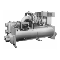
Fig. 1 – Model YK MaxE™ Chiller ................................................................ 5
Fig. 2 – Dimensions (P Compressors – Ft.-In.) ............................................ 6
Fig. 3 – Dimensions (P Compressors – Metric)............................................ 7
Fig. 4 – Dimensions (H Compressors – Ft.-In.)............................................ 8
Fig. 5 – Dimensions (H Compressors – Metric) ........................................... 9
Fig. 6 – Dimensions (J Compressors – Ft.-In.)............................................. 10
Fig. 7 – Dimensions (J Compressors – Metric) ............................................ 12
Fig. 8 – Rigging ............................................................................................ 18
Fig. 9 – Neoprene Isolators (Ft.-In.) ............................................................. 19
Fig. 10 – Neoprene Isolators (Metric)............................................................. 20
Fig. 11 – Spring Isolators (Ft.-In.)................................................................... 21
Fig. 12 – Spring Isolators (Metric) .................................................................. 22
Fig. 13 – Schematic for a Typical Piping Arrangement................................... 24
Fig. 14 – Typical Refrigerant Vent Piping ....................................................... 25
Fig. 15 – Control Panel Positioning ................................................................ 26
Fig. 16 – Motor Connections (E.M. Starter).................................................... 27

 Loading...