YORK INTERNATIONAL
10
FORM 160.73-N1 (904)
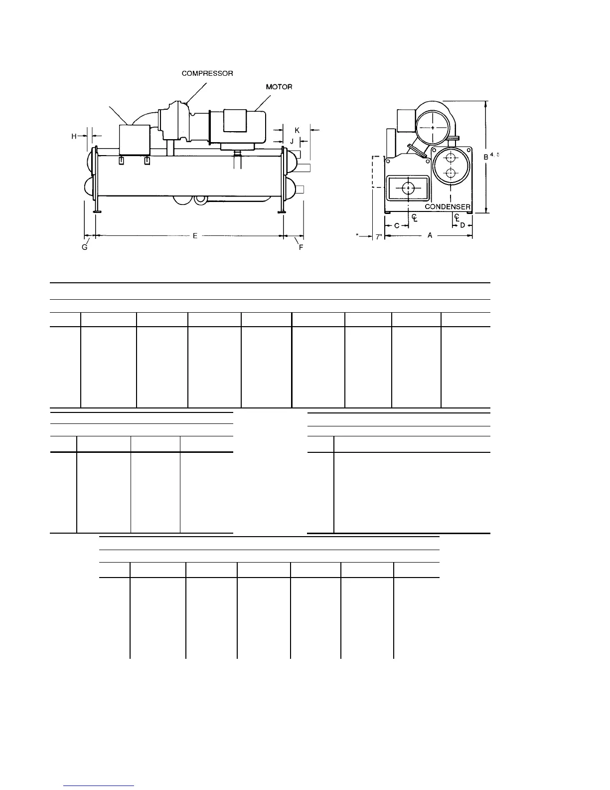
FIG. 6 – DIMENSIONS – J COMPRESSOR UNITS (FT.–IN.)
J1/J2 COMPRESSORS
EVAPORATOR – CONDENSER SHELL CODES
G-G G-H H-G H-H H-J J-H J-J T-T
A 7'–6" 7'–10" 7'–10-1/2" 8'–2-1/2" 8'–6-1/2" 8'–11" 9'–1" 9'–1"
B 9'–3-3/4" 9'–9-3/4" 9'–3-3/4" 9'–9-3/4" 9'–9-3/4" 9'–9-3/4" 9'–9-3/4" 9'–9-1/2"
C 2'–0" 2'–0" 2'–2-1/4" 2'–2-1/4" 2'–2-1/4" 2'–5-1/2" 2'–5-1/2" 2'–5-1/2"
D 1'–9" 1'–11" 1'–9" 1'–11" 2'–1" 1'–11" 2'–1" 2'–1"
E 14'–0" 14'–0" 14'–0" 14'–0" 14'–0" 14'–0" 14'–0" 16'–0"
F 1'–11-3/4" 1'–11-3/4" 1'–11-3/4" 1'–11-3/4" 1'–11-3/4" 1'–11-3/4" 1'–11-3/4" 1'–11-3/4"
G 1'–2-3/4" 1'–2-3/4" 1'–2-3/4" 1'–2-3/4" 1'–2-3/4" 1'–2-3/4" 1'–2-3/4" 1'–2-3/4"
J3 COMPRESSORS
EVAPORATOR – CONDENSER SHELL CODES
H-H H-J J-H
A 8'–2-1/2" 8'–6-1/2" 8'–9"
B 9'–8-3/4" 10'–0-3/4" 9'–8-3/4"
C 2'–2-1/4" 2'–2-1/4" 2'–5-1/2"
D 1'–11" 2'–1" 1'–11"
E 14'–0" 14'–0" 14'–0"
F 1'–11-3/4" 1'–11-3/4" 1'–11-3/4"
G 1'–2-3/4" 1'–2-3/4" 1'–2-3/4"
J3/J4 COMPRESSORS
EVAPORATOR – CONDENSER SHELL CODES
J-J T-T T-V V-T V-V W-V
A 9'–1" 9'–1" 9'–6" 9'–1" 9'–6" 9'–11"
B 10'–0-3/4" 10'–0-3/4" 10'–5-3/4" 10'–0-3/4" 10'–5-3/4" 10'–5-3/4"
C 2'–5-1/2" 2'–5-1/2" 2'–5-1/2" 2'–5-1/2" 2'–5-1/2" 2'–8"
D 2'–1" 2'–1" 2'–3-1/2" 2'–1" 2'–3-1/2" 2'–3-1/2"
E 14'–0" 16'–0" 16'–0" 16'–0" 16'–0" 16'–0"
F 1'–11-3/4" 1'–11-3/4" 1'–11-3/4" 1'–11-3/4" 1'–11-3/4" 2'–0-3/4"
G 1'–2-3/4" 1'–2-3/4" 1'–2-3/4" 1'–2-3/4" 1'–2-3/4" 1'–4-1/2"
NOTES:
1. All dimensions are approximate. Certifi ed dimensions are avail able on request.
2. For compact water boxes (shown above), determine overall unit length by adding water box depth to tube sheet length.
3. Water nozzles can be located on either end of unit. Add 1/2" (13 mm) to nozzle length for fl anges connections.
4. To determine overall height, add 7/8" (22 mm) for isolators.
5. Use of motors with motor hoods may increase overall unit di men sions.
J COMPRESSOR UNITS
LD03887
* Operating
Location of
Control Cen ter
on Evap o ra tor
Codes G thru
W.
EVAPORATOR
OPTIVIEW™
CONTROL
CENTER
J5 COMPRESSORS
EVAPORATOR – CONDENSER SHELL CODES
X-X
A 10'–3"
B 11'–5"
C 2'–8"
D 2'–5-1/2"
E 18'-0"
F 2'–0-3/4"
G 1'–4-3/4"

 Loading...