FORM 160.73-N1 (904)
7
YORK INTERNATIONAL
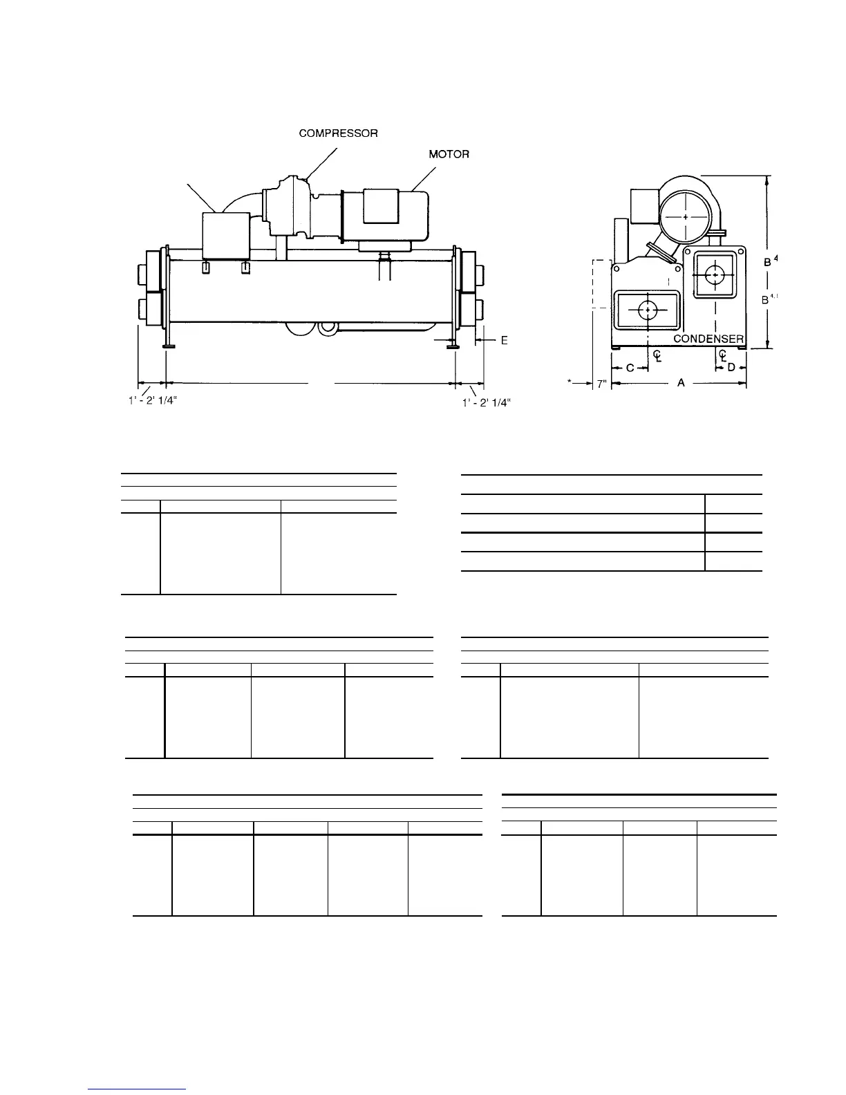
NOTES:
1. All dimensions are approximate. Certifi ed dimensions are avail able on request.
2. For compact water boxes (shown above), determine overall unit length by adding water box depth to tube sheet length.
3. Water nozzles can be located on either end of unit. Add 13 mm (1/2 inch) to nozzle length for fl anges connections.
4. To determine overall height, add 22 mm (7/8 inch) for isolators.
5. Use of motors with motor hoods may increase overall unit di men sions.
FIG. 3 – DIMENSIONS – P COMPRESSOR UNITS (mm)
LD03885
* Operating Location
of Control Center on
Evap o ra tor Codes G thru
W.
P COMPRESSOR UNITS
F
OPTIVIEW™
CONTROL
CENTER
EVAPORATOR
P8 COMPRESSOR
EVAPORATOR–CONDENSER SHELL CODES
E–E F–F G–G H–H
A 2,108 2,108 2,299 2,299
B 3,137 3,137 3,289 3,289
C 610 610 641 641
D 445 445 508 508
E 378 378 397 397
F 3,658 4,877 3,658 4,877
P9 COMPRESSOR
EVAPORATOR–CONDENSER SHELL CODES
F–F G–G H–H
A 2,108 2,299 2,299
B 3,045 3,200 3,200
C 610 641 641
D 445 508 508
E 378 379 397
F 4,877 3,658 4,877
P1, P2, P3, P4 COMPRESSORS
EVAPORATOR–CONDENSER SHELL CODES
A–A B–B
A 1,676 1,676
B 2,077 2,077
C 445 445
D 394 394
E 143 143
F 3,658 4,877
P5 COMPRESSOR
EVAPORATOR–CONDENSER SHELL CODES
A–A B–B C–C
A 1,676 1,676 1,880
B 2,248 2,248 2,299
C 445 445 495
D 394 394 445
E 143 143 143
F 3,658 4,877 3,658
P6, P7, Q7 COMPRESSOR
EVAPORATOR–CONDENSER SHELL CODES
C–C D–D
A 1,880 1,880
B 2,299 2,299
C 495 495
D 445 445
E 143 143
F 3,658 4,877
ADDITIONAL OPERATNG HEIGHT CLEARANCE
TYPE OF CHILLER MOUNTING M
NEOPRENE PAD ISOLATORS 44
SPRING ISOLATORS 25mm DEFLECTION 25
DIRECT MOUNT 19

 Loading...