JOHNSON CONTROLS
15
FORM 155.31-ICOM2.EN.UL
ISSUE DATE: 12/21/2018
2
The principle of refrigeration is the exchange of heat
and, in absorption liquid chilling, there are four basic
heat exchange surfaces: the evaporator, the absorber,
the generator, and the condenser. See Figure 10 on
page 31.
Like any refrigeration system, absorption chilling uses
evaporation and condensation to remove heat. The ab-
sorption cycle uses water as the refrigerant and lithium
bromide (LiBr) as the absorbent. The entire process oc-
curs in an almost complete vacuum.
CHILLER COMPONENTS
The absorption chiller consists of the following com-
ponents:
• evaporator
• absorber
• condenser
• generators
• solution heat exchangers to heighten the cycle
efciency
• pumps to circulate the refrigerant and solution in
the cycle
• purge unit to remove non-condensable gas from
the machine
CONTROL PANEL
The absorption chiller comes with a factory mounted
and pre-wired control system. The control panel en-
closure is equipped with a hinged access door with
lock and key. The control panel includes a touch panel
showing all system parameters in various languages
with numeric data in metric units. For details of the
control panel, see SECTION 6 – OPERATION.
The unit is also equipped with two methods to start and
stop operations:
• touch panel
• external signal
SECTION 2 – PRODUCT DESCRIPTION
NOTE: Conrm the main power switch
is within 6.56 feet (2 meters) of the
ground. If not, please install the opera-
tion platform.
WARNING: Turn off the power supply
by the handle breaker when opening the
control panel.
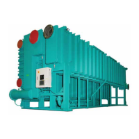
COMPONENTS
A Evaporator
B Absorber
C Condenser
D Cooling Water Outlet
E Low Temperature generator
F High Temperature Generator
G Steam Inlet
H Solution Pump
I Cooling Water Inlet
J Touch Panel Display
K Control Panel
L Chilled Water Inlet
M Chilled Water Outlet
LD22831
L
I
M
D
A
B
C
H
G
F
E
K
J
FIGURE 1 - DOUBLE EFFECT STEAM-FIRED ABSORPTION CHILLER CYCLE DIAGRAM

 Loading...