JOHNSON CONTROLS
110
FORM 201.30-ICOM1 (519)
ISSUE DATE: 05/22/2019
SECTION 6 - OPERATION
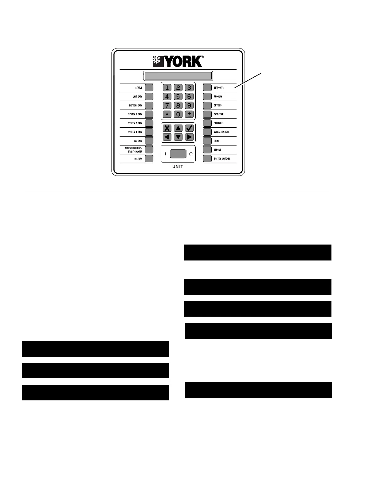
SETPOINTS KEY
FIGURE 53 - SETPOINTS KEY
SETPOINTS KEY
This message (above) will display the remote setpoint
and control, which automatically updates. If there is
no remote setpoint or range, these values will display
as ###.
SETPOINTS ◄DEF #### LO #### HI ####
MAXIMUM REMOTE TEMP RESET = ###.#°F
Heat Pump Applications
SETPOINTS ◄DEF #### LO #### HI ####
LOCAL HEATING SETPOINT = ###.# °F
SETPOINTS ◄DEF #### LO #### HI ####
LOCAL HEATING CONTROL RANGE = +/- #.# °F
SETPOINTS REMOTE SETPOINT = ###.# °F
REMOTE HEATING CONTROL RANGE = +/- #.# °F
This message (above) displays the remote setpoint and
hot water range, which automatically update. If there is
no remote setpoint or range, these values will display
as ###.
SETPOINTS ◄DEF #### LO #### HI ####
MAX. REMOTE HEATING TEMP RESET = ###.#°F
Minimum, maximum, and default values allowed are
listed in Table 37 on page 111.
Press the SETPOINTS key to program:
• Non-heat pump application cooling setpoints and
ranges.
• Heat pump application cooling/heating setpoints
and ranges.
Table 37 on page 111 contains the allowable tempera-
ture ranges for both applications. English units are ex-
act values while the metric units are approximate.
The SETPOINT entry screen is shown below. DEF
shows the chiller default, LO/HI show minimum and
maximum acceptable values. Press the SETPOINTS or
the ▼ key to display the next message.
Non-Heat Pump Applications
SETPOINTS ◄DEF #### LO #### HI ####
LOCAL COOLING SETPOINT = ###.# °F
SETPOINTS ◄DEF #### LO #### HI ####
LOCAL CONTROL RANGE = +/- #.# °F
SETPOINTS REMOTE SETPOINT = ###.# °F
REMOTE CONTROL RANGE = +/- #.# °F

 Loading...


