JOHNSON CONTROLS
27
SECTION 3 - HANDLING, STORAGE, INSTALLATION AND REASSEMBLY
FORM 201.30-ICOM1 (519)
ISSUE DATE: 05/22/2019
3
MOVING THE CHILLER FOR FORMS 1 AND 2
Prior to moving the unit, make sure that the installa-
tion site is suitable for installing the unit and is easily
capable of supporting the weight of the unit and all as-
sociated services.
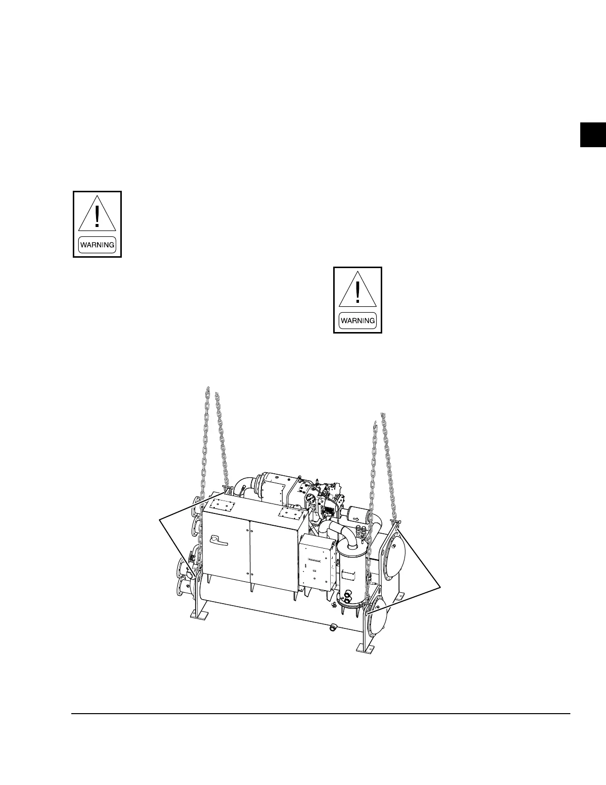
The unit is designed to be lifted using chains or cables.
The unit is provided with lifting eyes in the corners of the
end sheets, which can be attached directly using shackles
or safety hooks as shown in Figure 6 on page 28.
Improper Unit/Component Lift! Test
lift the unit/component approximately
24 in. (610 mm) to verify the proper
center of the gravity lift point. To avoid
dropping the unit/component, reposition
the lifting point if the unit/component
is not level. Failure to properly lift the
unit/component could result in death or
serious injury or possible equipment or
property-only damage.
RIGGING
The complete standard unit (Forms 1 and 2) is shipped
without skids. When optional skids are used, it may
be necessary to remove the skids so that the riggers
skates can be used under the unit end sheets to reduce
the overall height.
Each unit has provided lifting holes (two on each end
sheet), which should be used to lift the unit. Be care-
ful during rigging and handling to avoid damage to the
unit and its external connections. Lift only using the
holes specified.
The unit must be special ordered if it is necessary to
rig a unit on one end to permit lifting or dropping it
through a vertical passageway (e.g., an elevator shaft).
Never lift the entire unit with slings
around the compressor/motor assembly or
by the eyebolts in the tapped holes of the
compressor/motor assembly. Do not turn
the unit on its side for rigging or rig it
with the driveline in a vertical orientation.
FIGURE 7 - UNIT RIGGING FOR FORMS 1 AND 2
LD17277a
LIFTING
HOLES
LIFTING
HOLES

 Loading...


