JOHNSON CONTROLS
39
SECTION 3 - HANDLING, STORAGE, INSTALLATION AND REASSEMBLY
FORM 201.30-ICOM1 (519)
ISSUE DATE: 05/22/2019
3
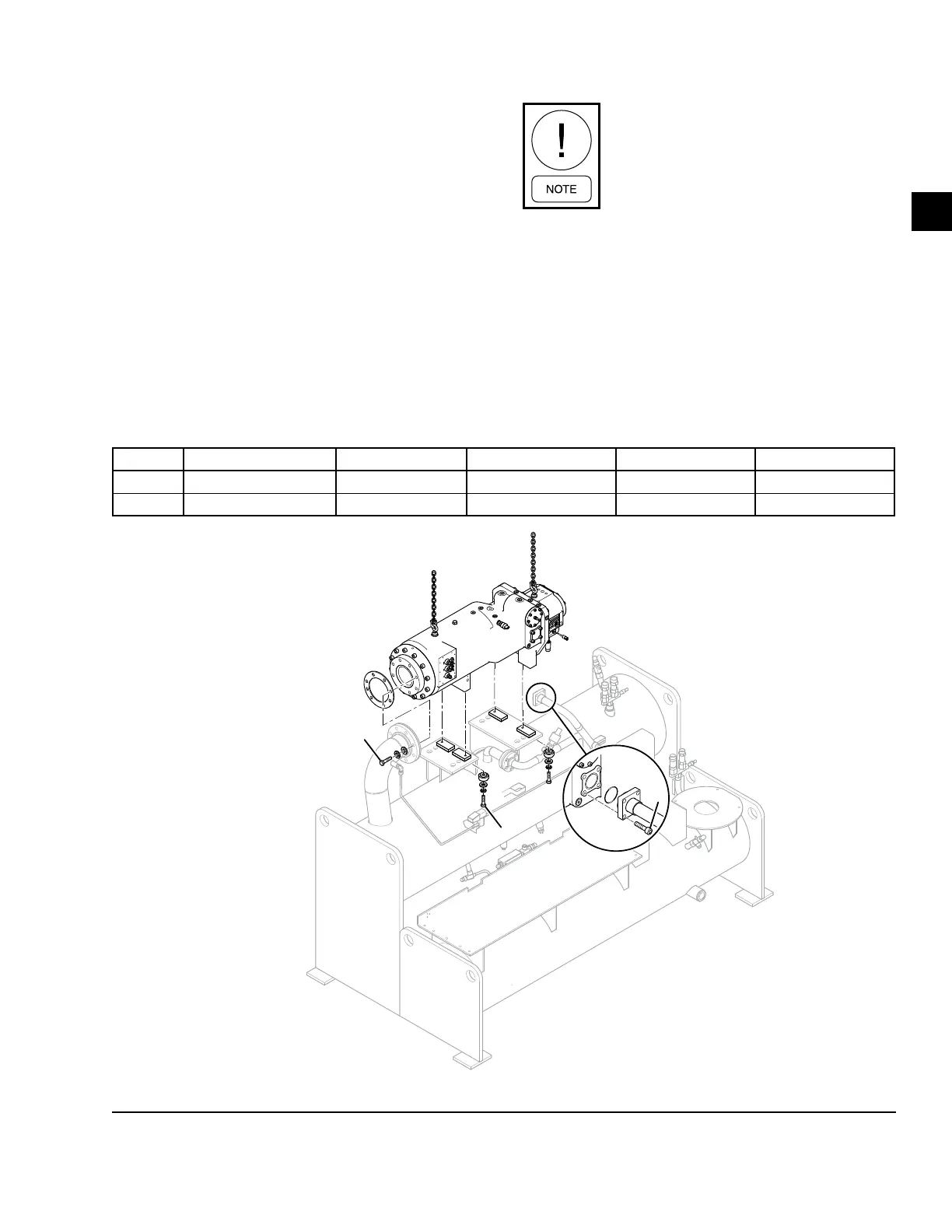
Installing Driveline Assembly
Use the following instructions to install the driveline
(compressor/motor) assembly as shown in Figure 18
on page 39.
1. Lift the compressor/motor assembly and remove
packing materials. Clean all sealing surfaces.
2. Carefully lower the compressor/motor assembly
onto the supports on the evaporator.
3. Install the suction gasket and loosely fasten the
compressor to the suction line.
4. Loosely fasten the compressor/motor assembly
to the supports on the evaporator with the proper
hardware. Do not tighten the bolts until all con-
nections are made to the compressor.
Specic shim pads will be bolted to the
compressor supports to satisfy the align-
ment between the compressor and system
piping.
Installing Economizer Piping to Compressor
Use the following instructions to install the piping to
the compressor as shown in Figure 18 on page 39.
1. Remove the shipping closures on the economizer
pipes, and clean all sealing surfaces.
2. Lubricate and install the new o-ring on this piping
at the compressor port end.
TABLE 7 - COMPRESSOR WEIGHT AND DIMENSIONS
PIN 9 COMPRESSOR SIZE WEIGHT (LB/KG) LENGTH (IN/MM) WIDTH (IN/MM) HEIGHT (IN/MM)
F 145mm 1113 (505) 42 (1064) 18.9 (480) 18.3 (466)
G 151mm 1405 (637) 46 (1168) 18.9 (480) 19.03 (483)
Refer to Table 4 on page 32
for Torque Specications.
LD17758
C
D
E
FIGURE 18 - DRIVELINE (COMPRESSOR/MOTOR) ASSEMBLY

 Loading...


