20
`
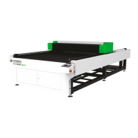
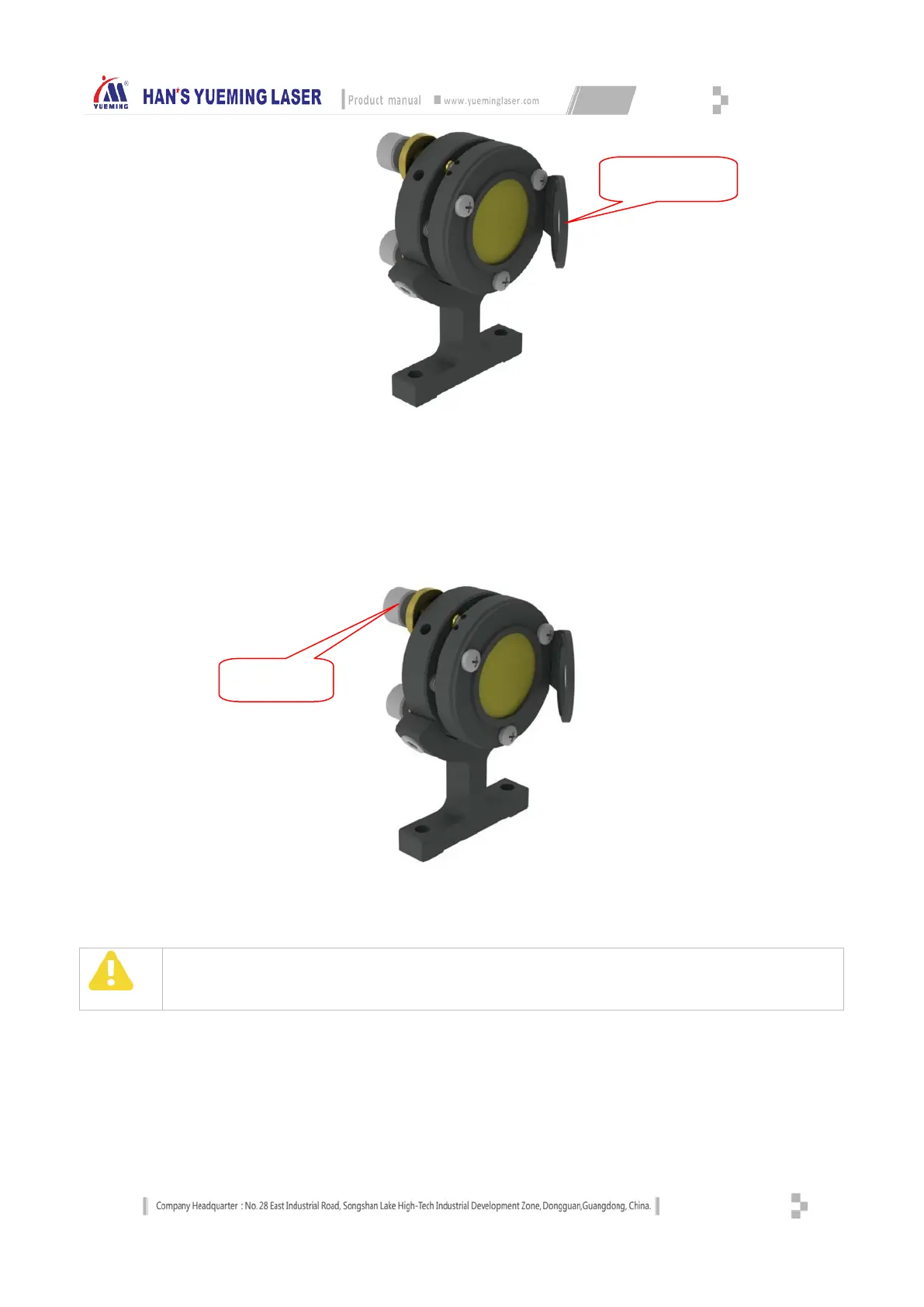
Reflector Holder
Stick a layer of adhesive paper on the inlet of 2# reflector holder, press surrounding of the inlet to make
the contour of the inlet appear on the adhesive paper, adjust the screws of 1# reflector holder, and
irradiate the laser beam of 1# reflector to the center of 2# reflector; if needed, adjust three adjustment
screws to make the laser beam focus on the center of 2# reflector, as shown below:
Optical Path Adjustment
Attention
The positions of the light spots above are recommended to emit at the center of lens, but not the edge. In case of
being at the edge, further adjustment is needed till being at the center.
When adjusting the third and fifth reflector, move the cutting head assembly to the leftmost and
rightmost of the beam. Affix a layer of tape on the incident light port of the cutting head, burst laser at
the burst leftmost and rightmost of the beam, to make the laser beam on the tape affixed on the
incident light port of the cutting head and ablate traces of light spot, adjust the screws of the front
reflector holder so that the spots superpose in the center of the incident light port;
Lens pitch angle
adjustment screw
center of this hole